How do you test an alternator?
I have a unit on an old 1275 engine I am considering fitting to my 1098 but want to know if it is working before using.
Dave
testing an alternator
Forum rules
By using this site, you agree to our rules. Please see: Terms of Use
By using this site, you agree to our rules. Please see: Terms of Use
 Websites:
 How's that going to work then? You need the small wire connected at the very least for it to work! And I seem to recall reading it's not good for them to run without being hooked up.Peetee wrote:I would bolt it in situ to the engine, attatch the fan belt but leave the wiring off. This should only take 20 mins or so. Put a voltmeter across the terminal and see what its producing.
By the time you've fitted it to an engine you might as well wire it up and measure the voltage at the battery, or even where the thick brown wires are connected (solenoid usually). You get the added benefit of charging the engine while testing, if it's any good
-
Peetee
- Minor Legend
- Posts: 3428
- Joined: Fri Nov 22, 2002 9:20 am
- Location: Southampton
- MMOC Member: No
Why shouldn't it?How's that going to work then
If the car hasn't had an alternator fitted before then the wiring needs to be changed. That's going to be a lot of hassle for Dave if he then finds it's not working and he has to go back to using his dynamo.
Older and more confused than I could ever imagine possible.
-
Willie
- Minor Legend
- Posts: 3204
- Joined: Tue Feb 12, 2002 12:00 am
- Location: S E London
- MMOC Member: No
testing
On all early type Alternators it was certain death to operate them
without being 'on load' i.e. connected to the battery. I believe later
types are more accomodating.
without being 'on load' i.e. connected to the battery. I believe later
types are more accomodating.
Willie
[img]http://i39.photobucket.com/albums/e197/wuzerk/mo9.jpg[/img]
[img]http://i39.photobucket.com/albums/e197/wuzerk/mo9.jpg[/img]
Well, for a start if it hasn't got a 12v feed into the alternator to fire up the wirings, it ain't going to work!Peetee wrote:Why shouldn't it?How's that going to work then
Fit alternator. Wire up a 2W bulb (bulb not essential I believe, so long as there is a 12v feed into teh alternator) from a positive to the small terminal on the alternator. Run a wire connected to both larger terminals to the live on the start solenoid. fire up engine and take readings. A plug and some wire chopped off a car at the scrappy will do fine for this so long as it's long enough to reach the solenoid, and it can be twisted together/ wrapped round terminals to suit for the sake of a quick test. Adds maybe 5 minutes to the job, and the bulb will be a test bench ignition warning light which is an added bonus.If the car hasn't had an alternator fitted before then the wiring needs to be changed. That's going to be a lot of hassle for Dave if he then finds it's not working and he has to go back to using his dynamo.
And yes, as Willie says, certainly older alternators don't much like being run without being hooked up, and I personally wouldn't risk my luck with newer ones either for the sake of a few minutes and a couple of bits of wire.
-
Cam
- Moderator

- Posts: 5109
- Joined: Mon May 20, 2002 1:00 am
- Location: Stoke-on-Trent, Staffordshire, UK
- MMOC Member: No
Electronics is just 'little electrics', but the trouble is that being small, you can cram loads more systems and bits together so it looks complicated, but when you break it down it's just electrics... oh and all held together with magic.Packedup wrote:Electrics are really simple and easy, electronics however are some esoteric trickery I will never get my head round.
testing an alternator the Heath Robinson way
Now all you knowledgeable people can you tell me what I am reading???
I made an alternator test bed
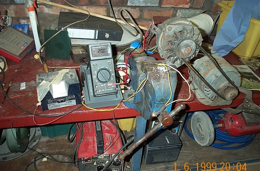
this consists of an old tumble dryer motor, a fan belt, alternator complete with tension adjuster (vice). I then took a 12v feed from my old battery charger and connected this to the small spade connector on alternator.
I then put a meter across the terminals +D and +B on the alternator. I switched everything on and the meter read around 20v. I thought this was a result until I noticed that even if I stopped the alternator spinninf the meter read about 20v. What is happening???
Dave
I made an alternator test bed
this consists of an old tumble dryer motor, a fan belt, alternator complete with tension adjuster (vice). I then took a 12v feed from my old battery charger and connected this to the small spade connector on alternator.
I then put a meter across the terminals +D and +B on the alternator. I switched everything on and the meter read around 20v. I thought this was a result until I noticed that even if I stopped the alternator spinninf the meter read about 20v. What is happening???
Dave
-
lowedb
- Minor Fan
- Posts: 243
- Joined: Mon Apr 19, 2004 1:01 pm
- Location: Hixon, Staffordshire
- MMOC Member: Yes
I notice the meter is autoranging. Are you sure it's not 20 millivolts?
You really need some load on the output to check what it's condition is like as it could have a duff diode and you'd still get an output but it would drop off under load. Also the regulator would have trouble operating with nowhere for the output to go.
I also think the bulb in series with the small terminal has to be there. It acts to limit the current on some versions, as the current through the bulb passes through the regulator and into the field coils. The one you have there (looks like an ACR) is almost certainly like this.
And finally, the output is not between the two terminals, it's between the big terminal and the body of the alternator.
Hello from Audrey, Beast, Tara, Robin, and of course Mog.
[img]http://i63.photobucket.com/albums/h125/lowedb/b12225ef.jpg[/img][img]http://i63.photobucket.com/albums/h125/lowedb/553409b1.jpg[/img]
[img]http://i63.photobucket.com/albums/h125/lowedb/b12225ef.jpg[/img][img]http://i63.photobucket.com/albums/h125/lowedb/553409b1.jpg[/img]