Page 1 of 1
Hazard Wiring
Posted: Mon Nov 17, 2025 12:55 pm
by radioactiveman
Hello all

I’ve just fitted a hazard warning kit to my car. The setup is a new flasher unit fed from a permanent live, which goes to a DPDT switch.
With the switch off, the indicator stalk is connected as normal.
With the switch on, the hazard flasher output is connected to both the left and right indicator circuits.
The problem I’ve run into is that by joining the left and right feeds together at the switch, when I use the indicator stalk both sides flash together. In hindsight that’s obvious, but it didn’t occur to me at the time!


My question is:
If I install a diode in each of the hazard feed wires (one on the left, one on the right), will that prevent the back-feed and stop both sides flashing when using the indicator stalk?
TYIA
Re: Hazard Wiring
Posted: Mon Nov 17, 2025 2:00 pm
by geoberni
Common mistake. if you haven't followed the paths in both directions.
I'm assuming it's your own design, from the way you described it.
Don't forget, the regulations required a way for you to know the difference between the Indicators and the Hazards being used. So you need a separate warning lamp.
That aside, connecting a Diode inline with each output from the Hazard Sw will sort it out.
Re: Hazard Wiring
Posted: Mon Nov 17, 2025 3:59 pm
by Bill_qaz
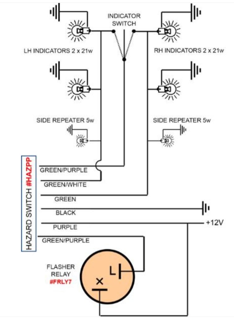
On a hazard kit the supply to the indicator switch is interrupted when hazards are active.when hazard switch off no interconnection between L+R indicator circuit.
- Screenshot_20220117-161550_Samsung Internet.jpg (61.46 KiB) Viewed 59396 times
Re: Hazard Wiring
Posted: Mon Nov 17, 2025 4:44 pm
by radioactiveman
geoberni wrote: ↑Mon Nov 17, 2025 2:00 pm
Common mistake. if you haven't followed the paths in both directions.
I'm assuming it's your own design, from the way you described it.
Don't forget, the regulations required a way for you to know the difference between the Indicators and the Hazards being used. So you need a separate warning lamp.
That aside, connecting a Diode inline with each output from the Hazard Sw will sort it out.
Thank you for your response, diodes it is! The design was inspired by a YouTube video on the 'Jodie, the Morris Minor Traveller' channel, however I decided I wanted a different looking switch, rather than the specific hazard one that he uses. It hadn't occurred to me that just splitting the switch output would of-course connect the two sides in normal operation.
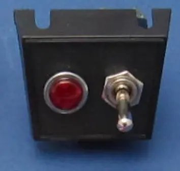
I've mounted it with a red light next to it. Something like:
- switch.jpg (14.81 KiB) Viewed 59384 times
It looks quite smart and I think satisfies the regulations. I get the car MOTd so I'll soon find out

Re: Hazard Wiring
Posted: Mon Nov 17, 2025 5:54 pm
by geoberni
Bill_qaz wrote: ↑Mon Nov 17, 2025 3:59 pm
On a hazard kit the supply to the indicator switch is interrupted when hazards are active.when hazard switch off no interconnection between L+R indicator circuit.
But he hasn't used a kit, he's built his own.
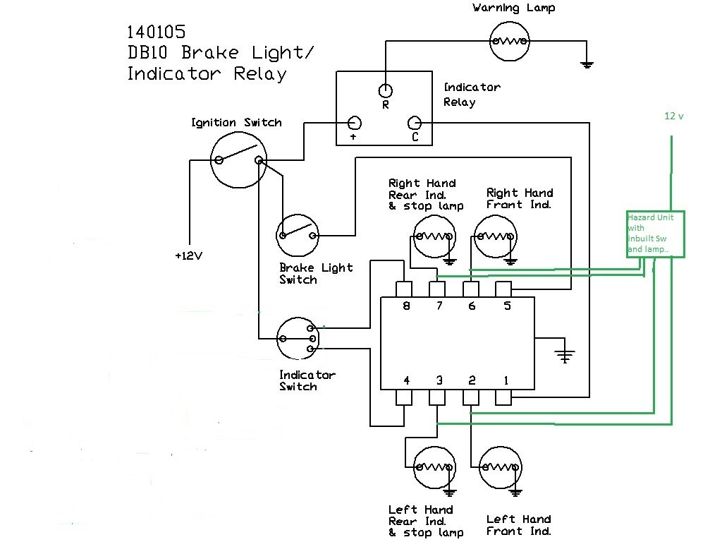
I fitted a 1970s Hazard Switch to mine, they didn't have the added function of the 'Indicator Inhibit' which seems to be standard on modern interpretations.
What they did have was 4 outputs so you could connect to each lamp individually

.
That was quite useful as it simplified the setup on my DB10 Indicator system.
- Hazard Lights basic.jpg (80.16 KiB) Viewed 59369 times
radioactiveman wrote: ↑Mon Nov 17, 2025 4:44 pm
Thank you for your response, diodes it is! The design was inspired by a YouTube video on the 'Jodie, the Morris Minor Traveller' channel, however I decided I wanted a different looking switch, rather than the specific hazard one that he uses. It hadn't occurred to me that just splitting the switch output would of-course connect the two sides in normal operation.
I've mounted it with a red light next to it. Something like:
It looks quite smart and I think satisfies the regulations. I get the car MOTd so I'll soon find out
As Bill mentioned, the modern Hazard Kit disables the Indicator system; have you incorporated that by using the DPDT?
Re: Hazard Wiring
Posted: Mon Nov 17, 2025 7:26 pm
by radioactiveman
geoberni wrote: ↑Mon Nov 17, 2025 5:54 pm
Bill_qaz wrote: ↑Mon Nov 17, 2025 3:59 pm
On a hazard kit the supply to the indicator switch is interrupted when hazards are active.when hazard switch off no interconnection between L+R indicator circuit.
But he hasn't used a kit, he's built his own.
I fitted a 1970s Hazard Switch to mine, they didn't have the added function of the 'Indicator Inhibit' which seems to be standard on modern interpretations.
What they did have was 4 outputs so you could connect to each lamp individually
.
That was quite useful as it simplified the setup on my DB10 Indicator system.
Hazard Lights basic.jpg
radioactiveman wrote: ↑Mon Nov 17, 2025 4:44 pm
Thank you for your response, diodes it is! The design was inspired by a YouTube video on the 'Jodie, the Morris Minor Traveller' channel, however I decided I wanted a different looking switch, rather than the specific hazard one that he uses. It hadn't occurred to me that just splitting the switch output would of-course connect the two sides in normal operation.
I've mounted it with a red light next to it. Something like:
It looks quite smart and I think satisfies the regulations. I get the car MOTd so I'll soon find out
As Bill mentioned, the modern Hazard Kit disables the Indicator system; have you incorporated that by using the DPDT?
Yes, the power to the stalk is connected across one side of the switch and the power from the new flasher is connected across the other side so when the hazard flasher is on the stalk no longer flashes or does anything at all.
Re: Hazard Wiring
Posted: Mon Nov 17, 2025 7:30 pm
by Bill_qaz
Berni, mine also has the DB10 but i have front an rear indicator off the same shared terminal (as brake lights no longer used as indicators) so two wires from hazard connected to L&R rather than 4 as its a kit unit.

Re: Hazard Wiring
Posted: Mon Nov 17, 2025 7:49 pm
by geoberni
Bill_qaz wrote: ↑Mon Nov 17, 2025 7:30 pm
Berni, mine also has the DB10 but i have front an rear indicator off the same shared terminal (as brake lights no longer used as indicators) so two wires from hazard connected to L&R rather than 4 as its a kit unit.
Basil originally had Trafficators but was re-loomed at some point to have DB10 (Trafficators were hanging there with no wiring), then altered to be like yours, but I've restored the full DB10 system plus the Trafficators.
Re: Hazard Wiring
Posted: Mon Nov 17, 2025 7:52 pm
by geoberni
radioactiveman wrote: ↑Mon Nov 17, 2025 7:26 pm
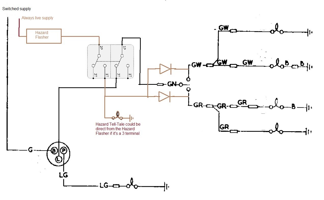
Yes, the power to the stalk is connected across one side of the switch and the power from the new flasher is connected across the other side so when the hazard flasher is on the stalk no longer flashes or does anything at all.
Something like this then, just for the benefit of anyone reading this who gets totally lost at the thought of electrics.

- DIY Hazard Wiring.jpg (73.96 KiB) Viewed 59276 times
Re: Hazard Wiring
Posted: Mon Nov 17, 2025 8:50 pm
by radioactiveman
geoberni wrote: ↑Mon Nov 17, 2025 7:52 pm
radioactiveman wrote: ↑Mon Nov 17, 2025 7:26 pm
Yes, the power to the stalk is connected across one side of the switch and the power from the new flasher is connected across the other side so when the hazard flasher is on the stalk no longer flashes or does anything at all.
Something like this then, just for the benefit of anyone reading this who gets totally lost at the thought of electrics.
DIY Hazard Wiring.jpg
Perfect!