Page 1 of 1
Brake Servo Pipe layout
Posted: Thu Oct 29, 2020 1:43 pm
by blue_cortina
Following on from the work I've been doing on my son's car whilst he is at Uni/Work
viewtopic.php?f=4&t=72662&start=40 I thought I'd start a new thread specifically about the next task I need to do. The car was bought earlier this year and since lockdown has been worked on to bring it up to the standard we want it in. The car currently has a servo fitted, it has all drums as standard. Upon doing the work in the mentioned thread I have worked out that the servo has only been used on the pipes going to the front wheels, this doesn't seem right to me and from all the threads I've read that is the majority opinion even if not everyone's opinion. I've decided to reroute so that the servo is applied to the whole circuit, i.e. both rear and front.
I think I need to do the following:
- Blank off the current original (non-servoed) rear pipe at rear of master with a 3/8 BSF bleed screw
- Split pipe after servo and fit new T piece (BSF/BSF/UNF ?)
- Route new pipe (somehow) to the rears, so they are also servoed
Guess my biggest question is what is the best way of connecting to the rears ?
- Bypass the old rear piping and fit new pipe to go from new T piece to rear flexi
- Or new pipe from new T piece to existing rear pipe at the rear of master cylinder - by taking it through a new hole in box section?
If anyone has photos of what they have done this would be appreciated.
(Edit: Looking around I can not find mixed thread T Pieces. So maybe go M10 or preferably UNF as UNF is used on the car anyway)
Re: Brake Servo Pipe layout
Posted: Thu Oct 29, 2020 2:42 pm
by geoberni
See this old topic.
viewtopic.php?t=52244#p493505
It should just be on a T-Piece to front and back.
Re: Brake Servo Pipe layout
Posted: Thu Oct 29, 2020 3:08 pm
by blue_cortina
Thanks for the link - I hadn't found that one. I'd downloaded and read through the Delphi instructions which that link screenshots. As I read more and more the mist is clearing!
I think my
main concern is the best way to go from new T Piece to rears... I'm starting to get parts ordered and putting things in place to sort this out.
Re: Brake Servo Pipe layout
Posted: Thu Oct 29, 2020 3:37 pm
by geoberni
Well always having had the Servo in Basil, I can't speak from personal experience of installing it, or what the original layout was exactly, but presumably there was a T-Piece to split the piping to Front and Rear, though where that was located in the car, I have no idea..
Here's what Basil's layout is now;
A = Connection from Servo Output
B = To Rear Brakes
C = To Front Brakes ( & Pressure Switch for Brake Lights)
D = From Master Cylinder to Servo Input
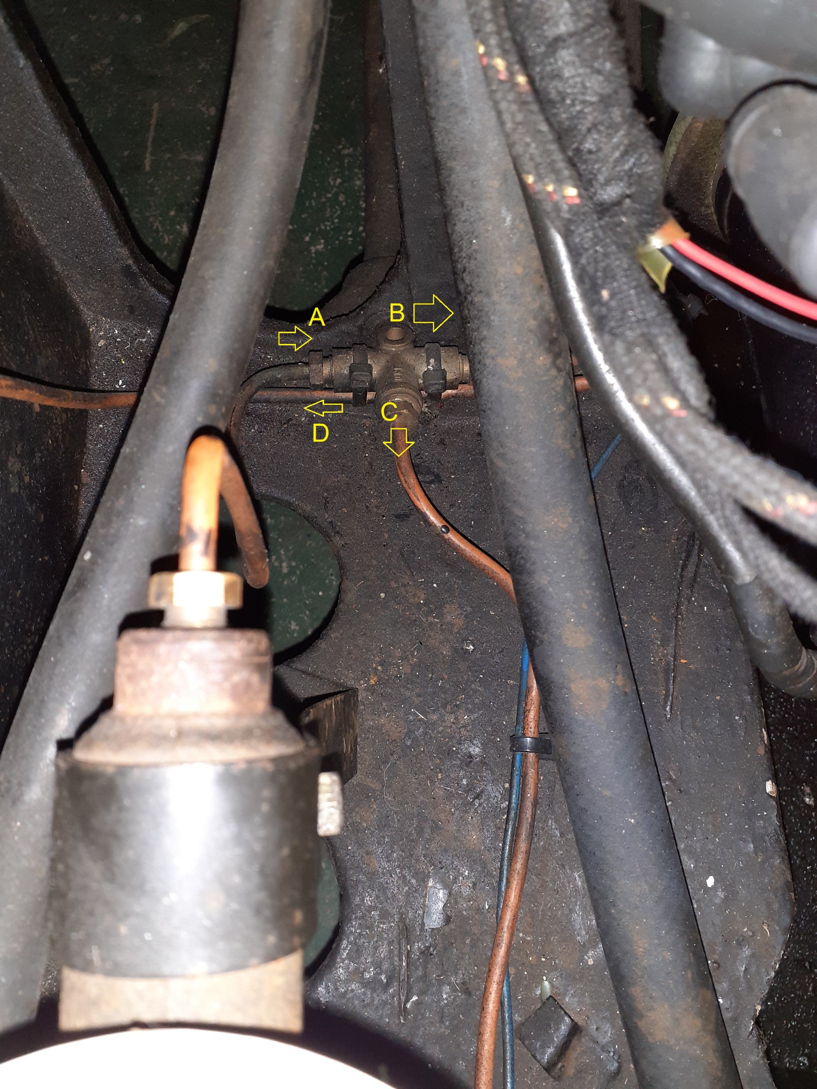
- 20201029_152014A.jpg (815.41 KiB) Viewed 1653 times
Re: Brake Servo Pipe layout
Posted: Fri Oct 30, 2020 1:44 pm
by blue_cortina
Thanks Geoberni. Here is the current piping in the engine bay. Servo is on drivers side RHD. Pipe at top is servo. 4Way splits front right/front/left and Brake switch. I need to split top pipe and get it to the rears somehow.
Re: Brake Servo Pipe layout
Posted: Fri Oct 30, 2020 3:44 pm
by geoberni
That's over-complex for only half the effect.

This is literally the diagram you need:
viewtopic.php?t=49248#p469397
That's exactly how Basil's is done. 2 x T in the circuit.
Re: Brake Servo Pipe layout
Posted: Fri Oct 30, 2020 10:51 pm
by kevin s
That pipe to the switch looks impossible to bleed too.
I can't remember why but there is a good reason why you should not servo only one circuit of a single circuit system , if you have dual circuit brakes it can be a useful way of correcting the brake imbalance that happens when you fit disc brakes (disc brakes give less braking for a given pedal effort than a twin leading shoe set up like minors have on the front) Ford did this on Corsairs and Cortina's when they introduced disc brakes. I remember doing loads of calcs on braking when at Uni, a light car like the Minor will need very little braking on the rear to avoid lock up under hard braking when unladen. (you always want the front to lock up before the back otherwise the back overtakes the front if braking hard on corners)
Kevin.
Re: Brake Servo Pipe layout
Posted: Sat Oct 31, 2020 2:04 pm
by blue_cortina
It hadn't even occurred to me that the brake switch had been put in strangely - but I should have guessed! I presume that the one shown here
viewtopic.php?t=30573#p312138 is the correct way of doing it. The only reason I can see that it might be on a separate pipe is if the switch is the wrong thread (?) I need to replumb some of that anyway so I can sort that out as well and if the switch is the wrong thread it could always be replaced with the right one.
And as for Cortinas and their brake systems, well.... Mk1 had all drums 62-64 and 65-66 they had front discs fitted and a new brake master cylinder which was had a bigger capacity, as per attached photo - funnily enough the Cortina had a similar set up for the brake switch

Re: Brake Servo Pipe layout
Posted: Sun Nov 01, 2020 6:10 pm
by kevin s
Yes it should be as the link you attached,bif buying a new switch get it from a reputable source, there are dodgy ones around which don't last.
Re: Brake Servo Pipe layout
Posted: Sun Nov 01, 2020 7:45 pm
by geoberni
Here's Basil's Switch arrangement.
(Perhaps the one in the old post you linked to was of a car without a servo, that would make sense for the number of connections. I'm sure someone versed in standard brake layout can confirm)
The feed from the T Piece in my previous photo comes in from the left of image, the pressure switch mounted directly on top of the '4-way T' and the 2 front brakes lines coming out of the 2 other connections.
Sometimes people can get an idea in their head of how something should be done and can't see the blindingly obvious option. Perhaps that's what the Servo installer did in your case, or as you wondered, they needed to adapt the size of the brake switch.
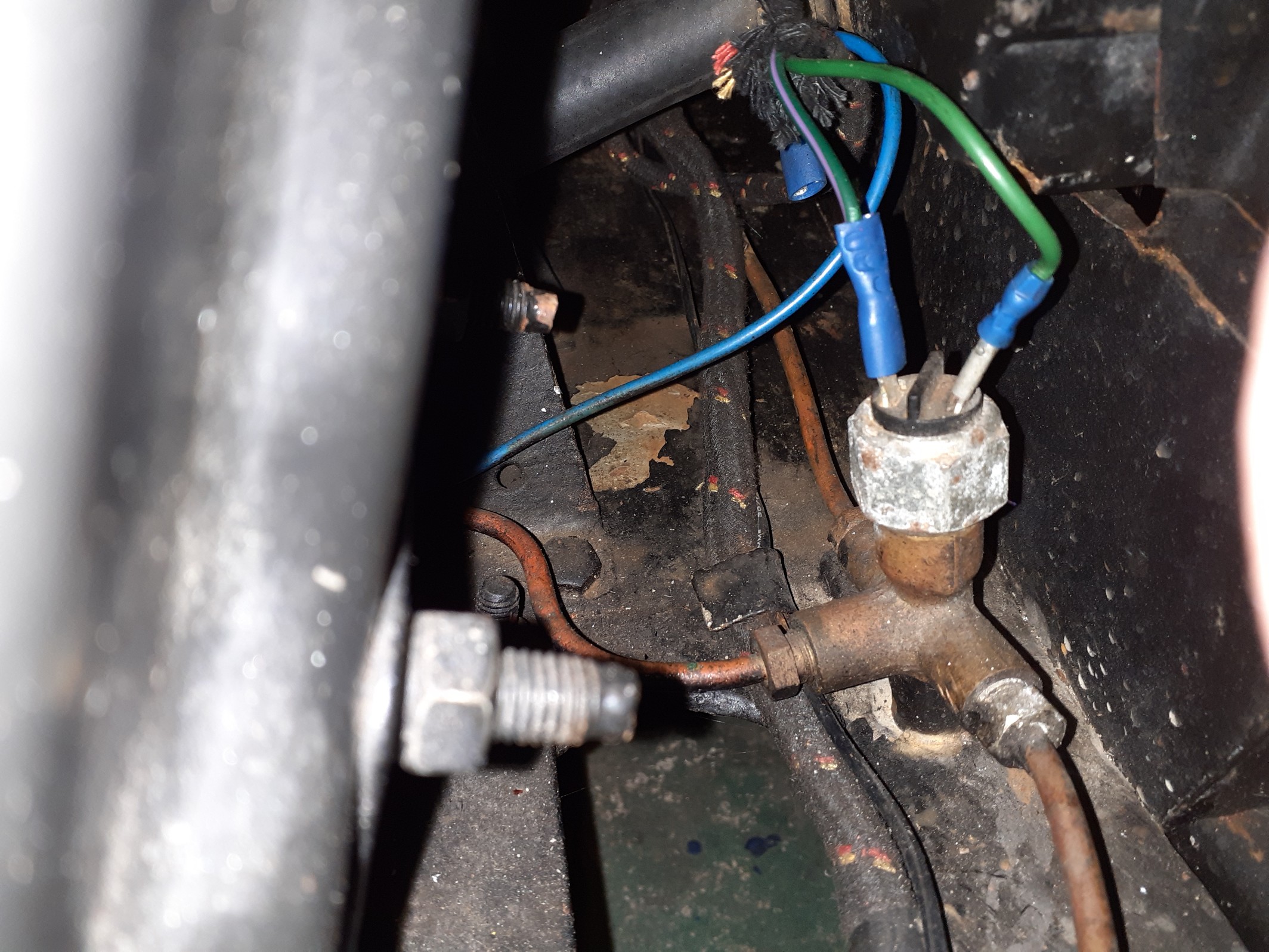
- 20201101_191902.jpg (696.03 KiB) Viewed 1500 times
Incidentally, in getting the photo, only on looking at the ones I'd taken, did I discover I have a little friend by the radiator....
If anyone is wondering why there is a loose blue cable in the image, that's because Basil's indicators were installed with the interim 1961-63 DB10 Relay system to flash the brake lights, but then had the DB10 bypassed so that the brake switch output went direct to the brake lights.
I've restored the DB10 Indicator system and that blue cable is the redundant line to the back. I've left it there in case I or anyone else might wish to go back to amber indicators on the rear.
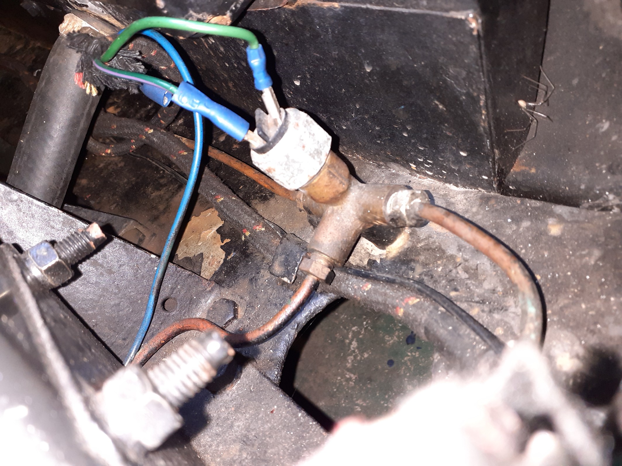
- 20201101_191831.jpg (784 KiB) Viewed 1500 times