Page 1 of 1
jacking beam
Posted: Fri Mar 27, 2020 7:48 pm
by stuupnorth
hi
thought I would show my home made jacking beam (was busy at work on sat LOL)
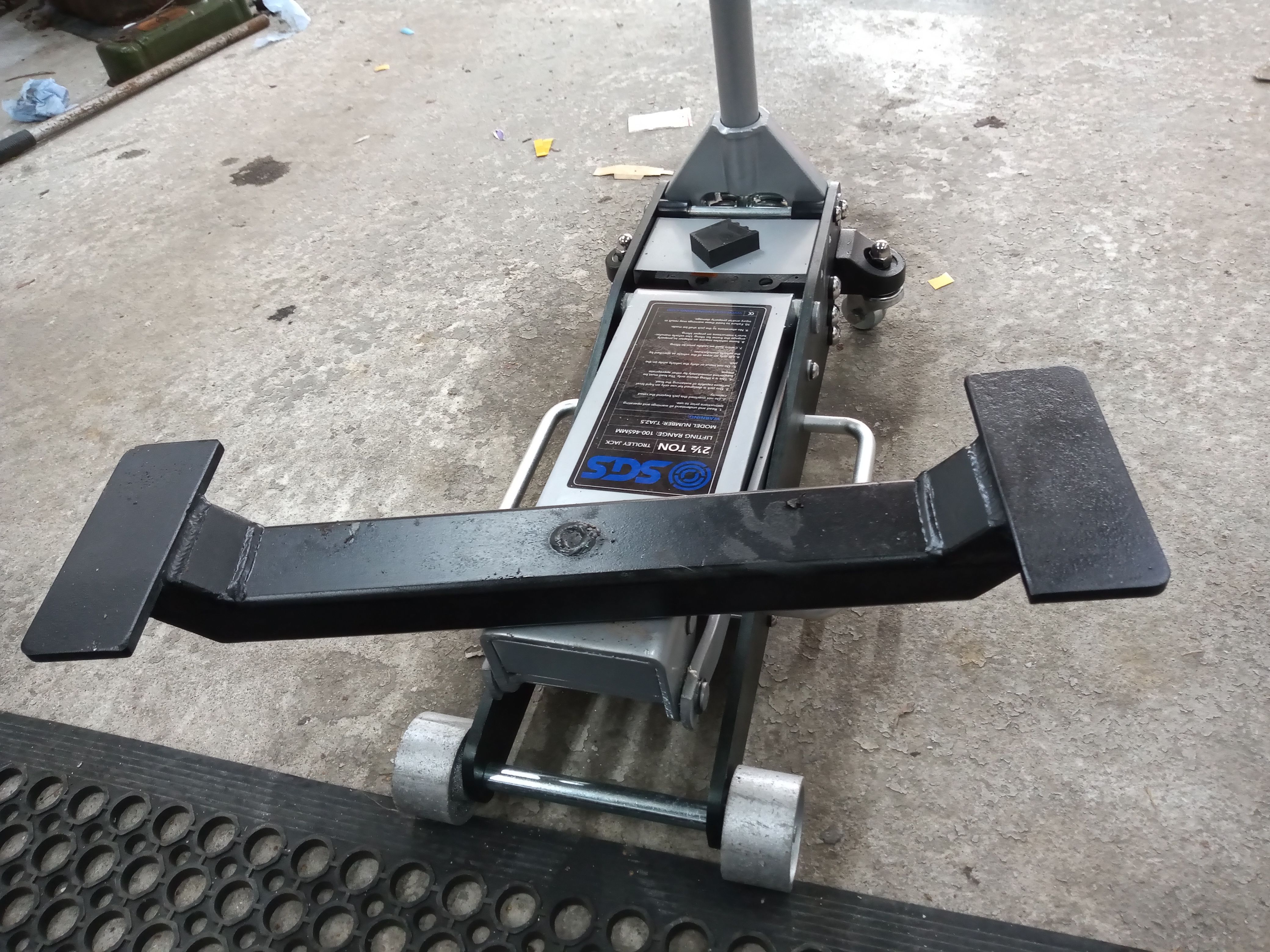
- IMG_20200321_120353104.jpg (4.28 MiB) Viewed 1910 times
fits under the two front chassis legs
Re: jacking beam
Posted: Fri Mar 27, 2020 8:52 pm
by les
Would you believe it, I've got a similar bar, for central jacking. You’ve made longer top bars, which is better.
Re: jacking beam
Posted: Fri Mar 27, 2020 8:55 pm
by KeithL
I reckon you've got the basis of a small business there. I'd buy one if the price was right.
Re: jacking beam
Posted: Fri Mar 27, 2020 9:27 pm
by stuupnorth
not sure what the boss would say LOL
Re: jacking beam
Posted: Fri Mar 27, 2020 10:18 pm
by les
Give him a percentage and he’d say ‘When can you start’?
Re: jacking beam
Posted: Fri Mar 27, 2020 10:37 pm
by jagnut66
hi
thought I would show my home made jacking beam (was busy at work on sat LOL)
Hi,
That looks to be a very good and useful idea.
If you aren't going to make any more yourself could you post up a 'how to', including what you made it out of and the measurements. I think others would be very grateful / interested to know.
Best wishes,
Mike.
Re: jacking beam
Posted: Sat Mar 28, 2020 9:51 am
by Declan_Burns
It looks very good! Well done. I would recommend adding some rubber pads.
Regards
Declan
Re: jacking beam
Posted: Sat Mar 28, 2020 10:20 am
by philthehill
Very good but - and this is no criticism but hopefully constructive suggestions...….
As you jack the car up the contact between the jacking beam chassis leg pads and the chassis leg is going to get less as they are both moving in different arcs. The contact could reduce to the point where the beam slips and then !@:%*.
There does need to be some form of articulation at the pad end of the beam to compensate for the different arcs.
A couple of flanges on the inside of the chassis leg plate to hold the beam central to the chassis legs would also be helpful.
As Declan suggests above heavy duty rubber pads on the plates will go a long way to reducing the beam slipping.
Phil
Re: jacking beam
Posted: Sat Mar 28, 2020 10:41 am
by les
Mine is a rather simpler affair, less professional even! It consists of a rectangular beam with a two inch high block of close laminate beech ply each end, topped with the afore mentioned rubber pads. I accept the point Phil makes although in most instances if feel the jack would roll forward to compensate for the arc, if of course, the jacking surface is level.
Re: jacking beam
Posted: Sat Mar 28, 2020 10:53 am
by philthehill
Les
It is the actual contact area between the chassis leg and lifting beam pad when the car is being lifted that concerns me!
You are right in that the jack should roll forwards or backwards to compensate for the lifting arc of the jack but it will not compensate for the movement arc of the chassis leg.
As the car is lifted the chassis leg goes from being near horizontal on the lifting pad to anything around 45 degrees but the lifting pad stays horizontal.
The chassis leg loading then is shifted to the rear edge of the lifting pad from which it is prone to slip or allows the edge of the lifting pad to dig into the chassis leg.
Phil
Re: jacking beam
Posted: Sat Mar 28, 2020 11:34 am
by les
Yep, missed that point !
Re: jacking beam
Posted: Sat Mar 28, 2020 8:43 pm
by stuupnorth
thanks for the constructive criticism guys
as we all know not to work under a car supported only with a jack
it was only made to lift the car up level to apply axle stands
as for making them move to keep the angle correct might look into it but my idea came from the beam jack
mot stations use,used today and no probs
i suppose if you really lifted the car up to the full jack height it might cause a problem
noted the idea of end stops on the plates and i am in the process of sourcing rubber for the plates
ill try and get some sizes and or diagram posted at some point
Stu
Re: jacking beam
Posted: Tue Apr 07, 2020 10:22 pm
by les
Whilst waiting for the measurements of the jacking bar that Stu has made, if someone wants a more diy model maybe the one shown would suffice.
The rectangular bar is approx 2 x 1 inches, (wall thickness 1/8 inch) Length equals the outside to outside measurement of front chassis legs. The timber pads are 1 1/2 inches high, to clear the sump, and about 3 x4 inches in size. Rubber topped.
Same issue that Phil highlighted but it works well and axle stands ensure safety
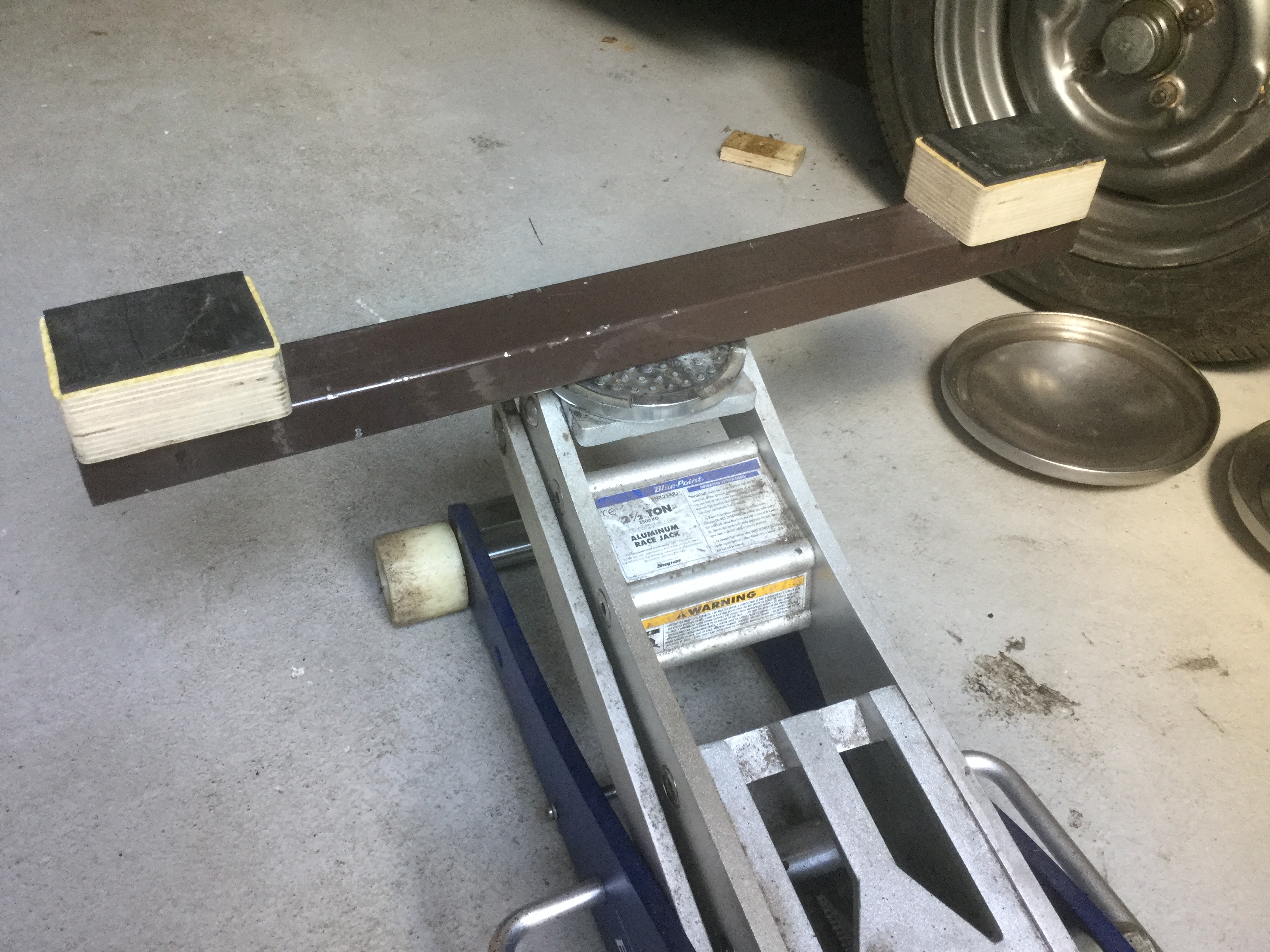
- B6910F52-6C2D-488A-AD68-F482DADA668C.jpeg (2.51 MiB) Viewed 1610 times
Re: jacking beam
Posted: Wed Apr 08, 2020 4:56 pm
by stuupnorth
hi
sorry for the delay
trying to upload pics but the site keeps telling me the file is too big to add to message!
i will try another way
Re: jacking beam
Posted: Thu Apr 09, 2020 6:28 pm
by stuupnorth
hi sorry its had to be done this way
this is the overall length of the beam
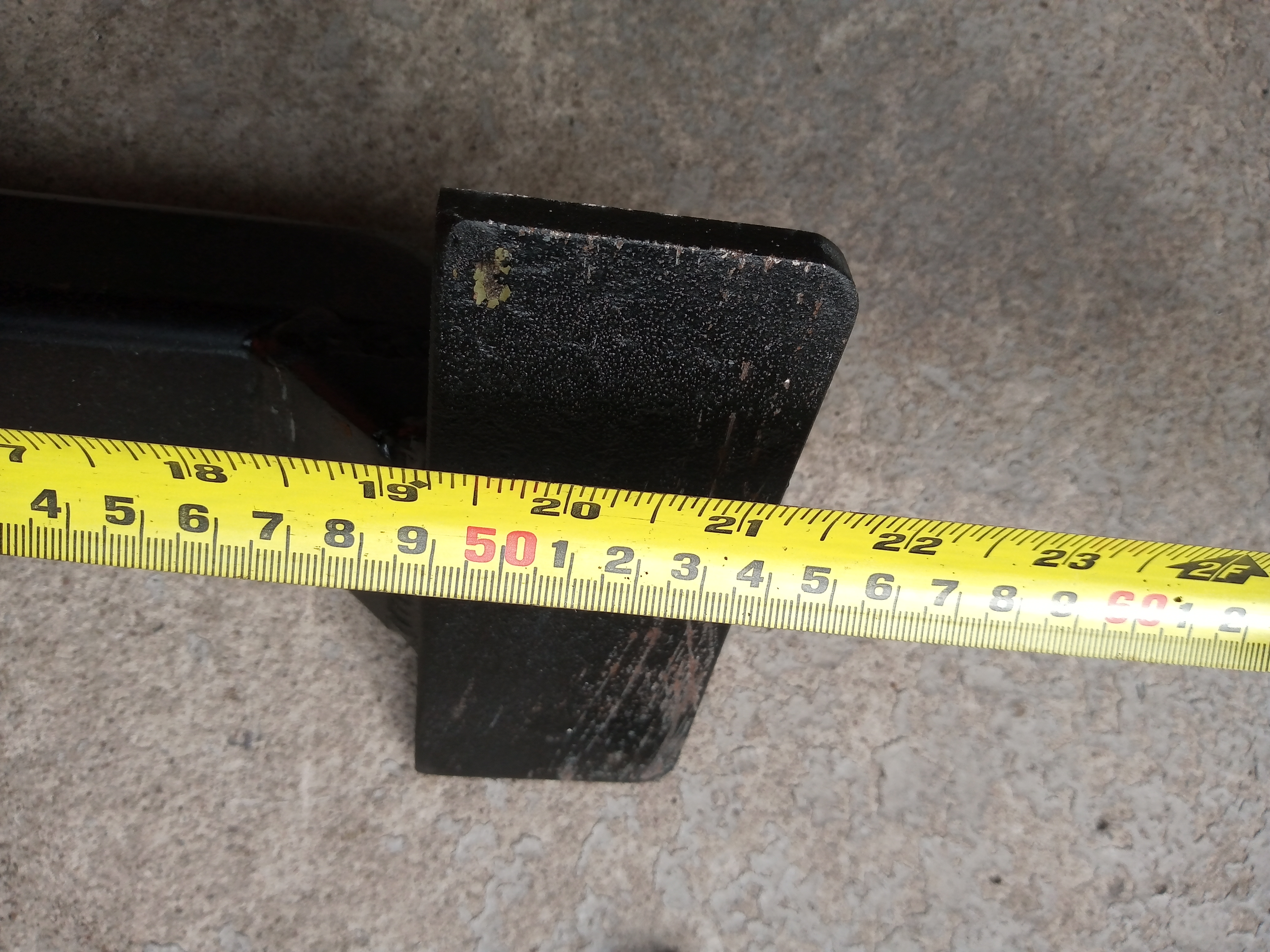
- IMG_20200409_121506711.jpg (3.53 MiB) Viewed 1518 times
this is the size of the top plate (i notched the box section to recess the plate you don't have to do that if your jack will allow the beam to fit under the car) i needed no more than 70mm in total height of the beam hence the plate being notched
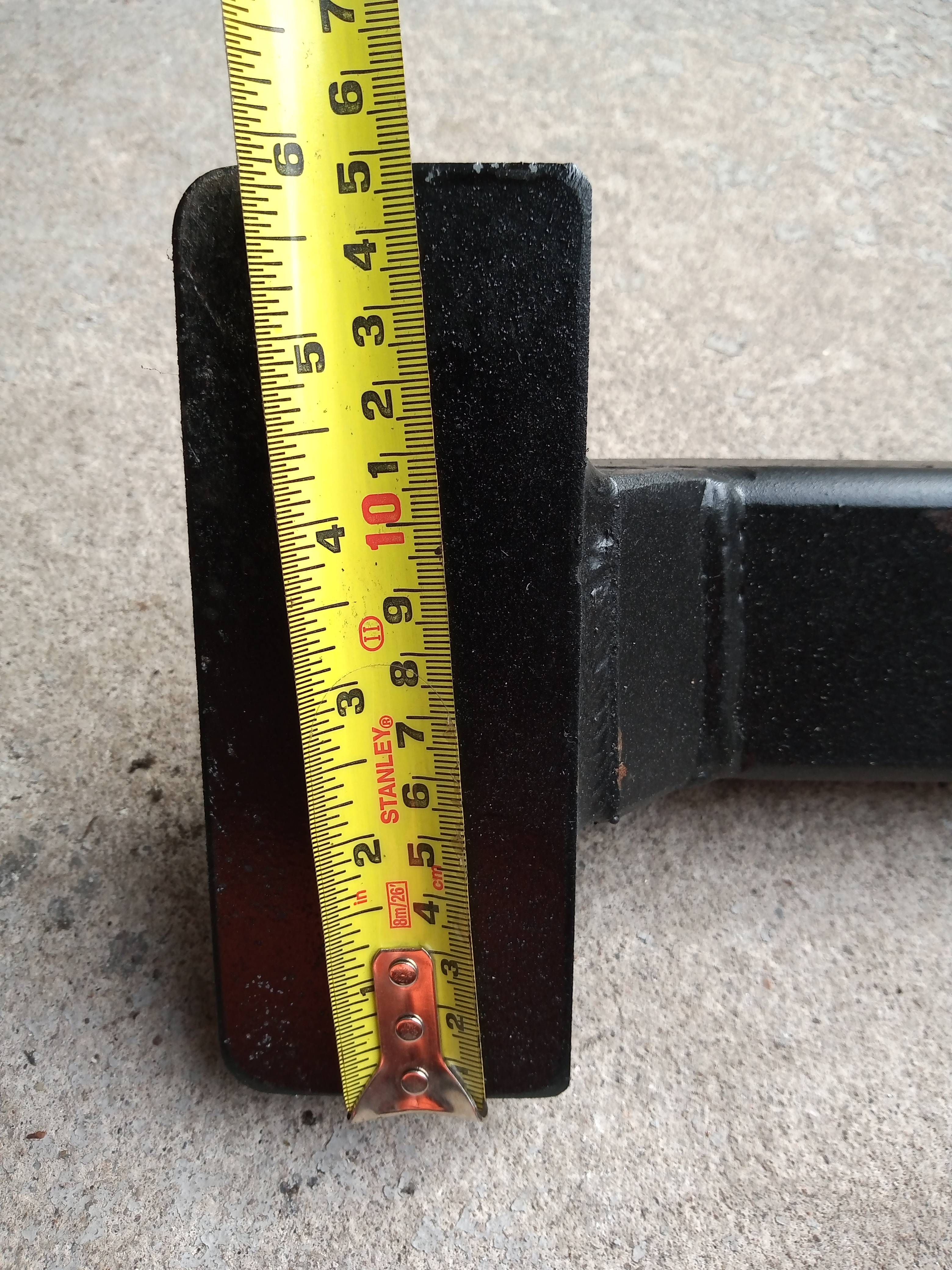
- IMG_20200409_121413398.jpg (4.25 MiB) Viewed 1518 times
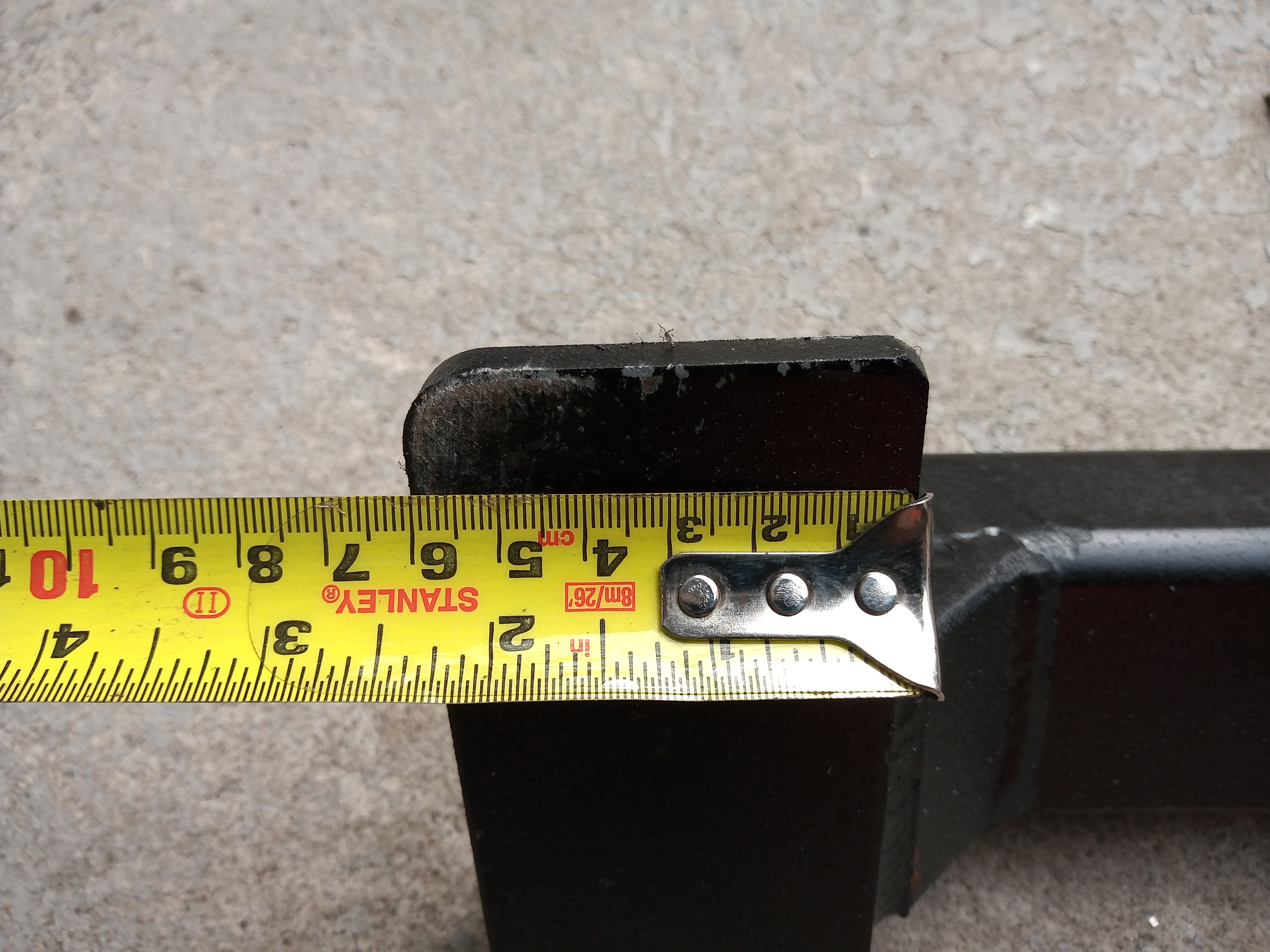
- IMG_20200409_121422804.jpg (3.09 MiB) Viewed 1518 times
this shows the size of box section which was 60 x 40 mm
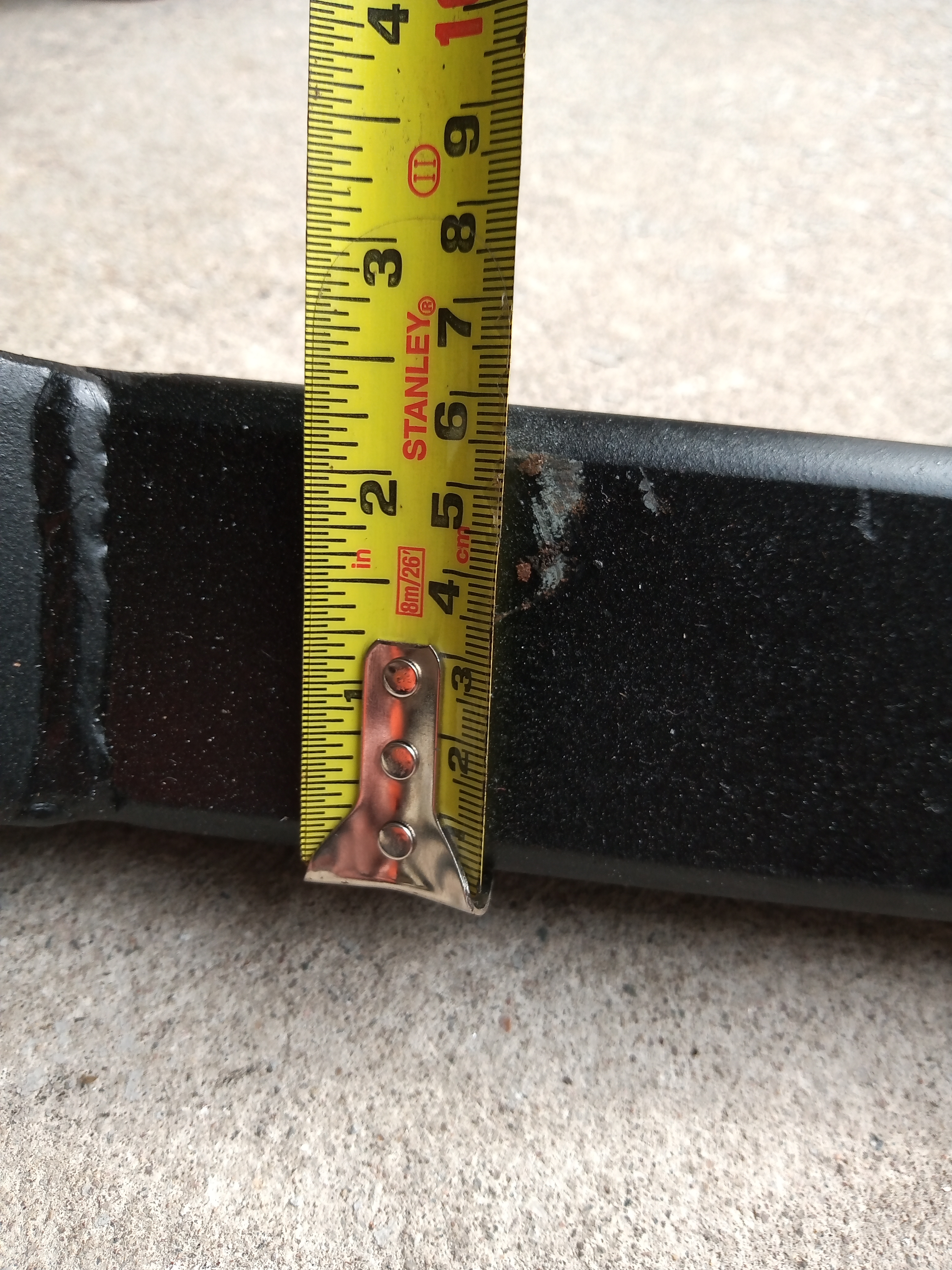
- IMG_20200409_121432866.jpg (3.76 MiB) Viewed 1518 times

- IMG_20200409_121443300.jpg (3.77 MiB) Viewed 1518 times
i'll add some more pics in the next post
Re: jacking beam
Posted: Thu Apr 09, 2020 6:43 pm
by stuupnorth
Re: jacking beam
Posted: Thu Apr 09, 2020 6:43 pm
by stuupnorth
being used
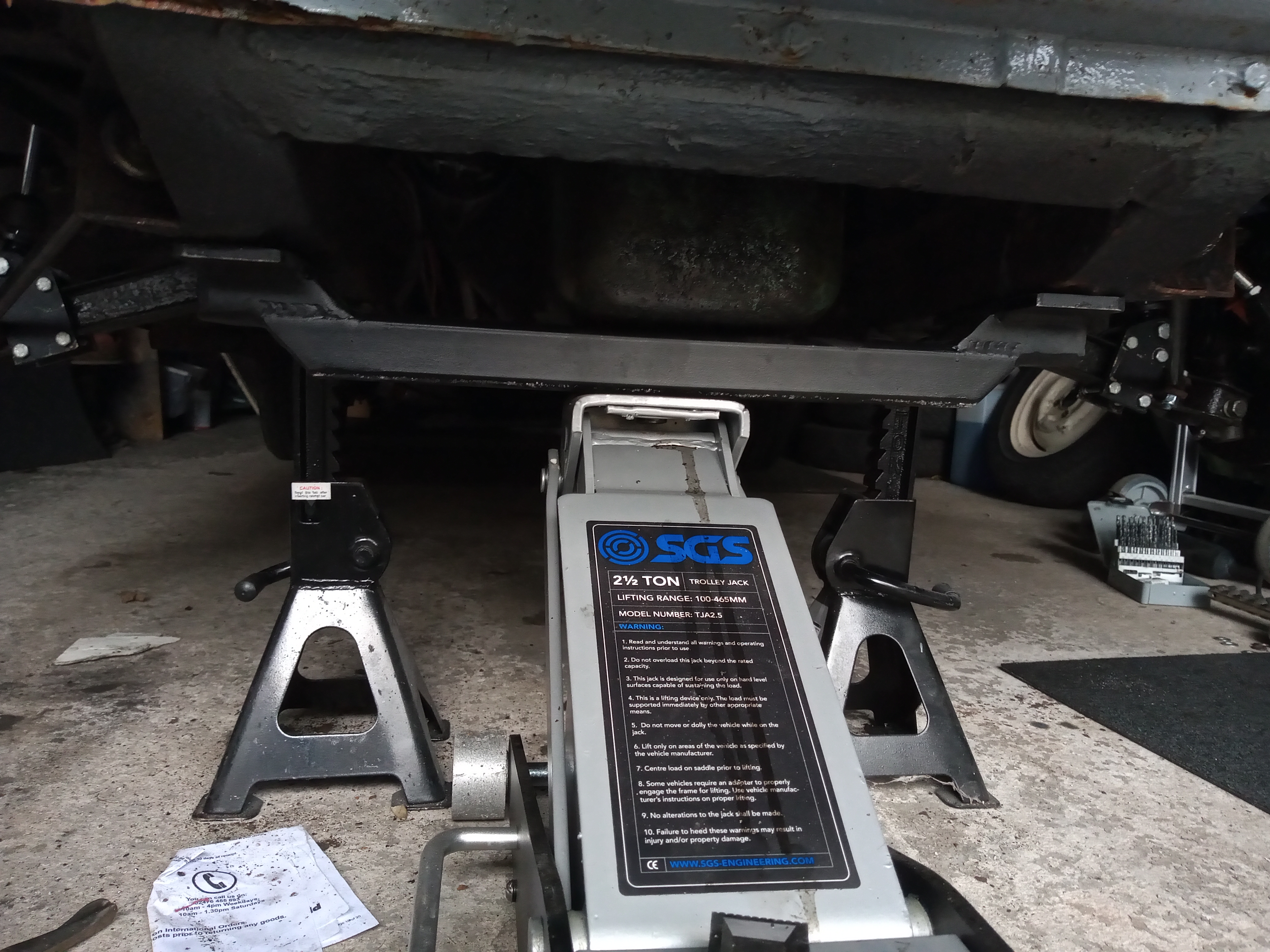
- IMG_20200409_183403913.jpg (3.71 MiB) Viewed 1515 times