Page 1 of 1
Rocker cover breather restricter
Posted: Sun Aug 28, 2016 2:10 pm
by philthehill
Just started to refurbish an 'A' Series BMC rocker cover with breather and found it was fitted with a removable (press fit) restrictor (when I say removable it should have been but the restrictor was well secured by years of gunge) fitted into the breather pipe from the inside. The restrictor has a 1/8" approx. hole in it pointing towards the rocker cover side so not a direct flow of fumes.
I cannot remember seeing one of these before - any comment appreciated.
The second photo shows what was left of the restrictor after removal and the usual breather pipe arrangement.
Phil[frame]

[/frame][frame]

[/frame]
Re: Rocker cover breather restricter
Posted: Mon Aug 29, 2016 10:34 am
by BLOWNMM
Phil
Is it possible the crankcase breathing had been modified by installing a PCV valve connecting the inlet manifold to the crankcase via either the timing cover or the side plate. If this were so then an open unrestricted rocker cover breather would not allow much vacuum to be developed in the crankcase and would allow the escape of oil from the crankshaft scroll. Maybee the restrictor was fitted to allow a compromise between purging of the crankcase and still providing some vacuum in the crankcase to restrict the escape of oil past the scroll.
Bob
Re: Rocker cover breather restricter
Posted: Tue Aug 30, 2016 7:46 am
by philthehill
Bob
Many thanks for your suggestions as to the restrictors fitment - you may well be right.
The rocker cover came as part of a semi dismantled 948cc engine with no identification as to its original fitment.
No doubt all will become clear in time.
Phil
Re: Rocker cover breather restricter
Posted: Tue Aug 30, 2016 8:39 am
by BLOWNMM
Phil
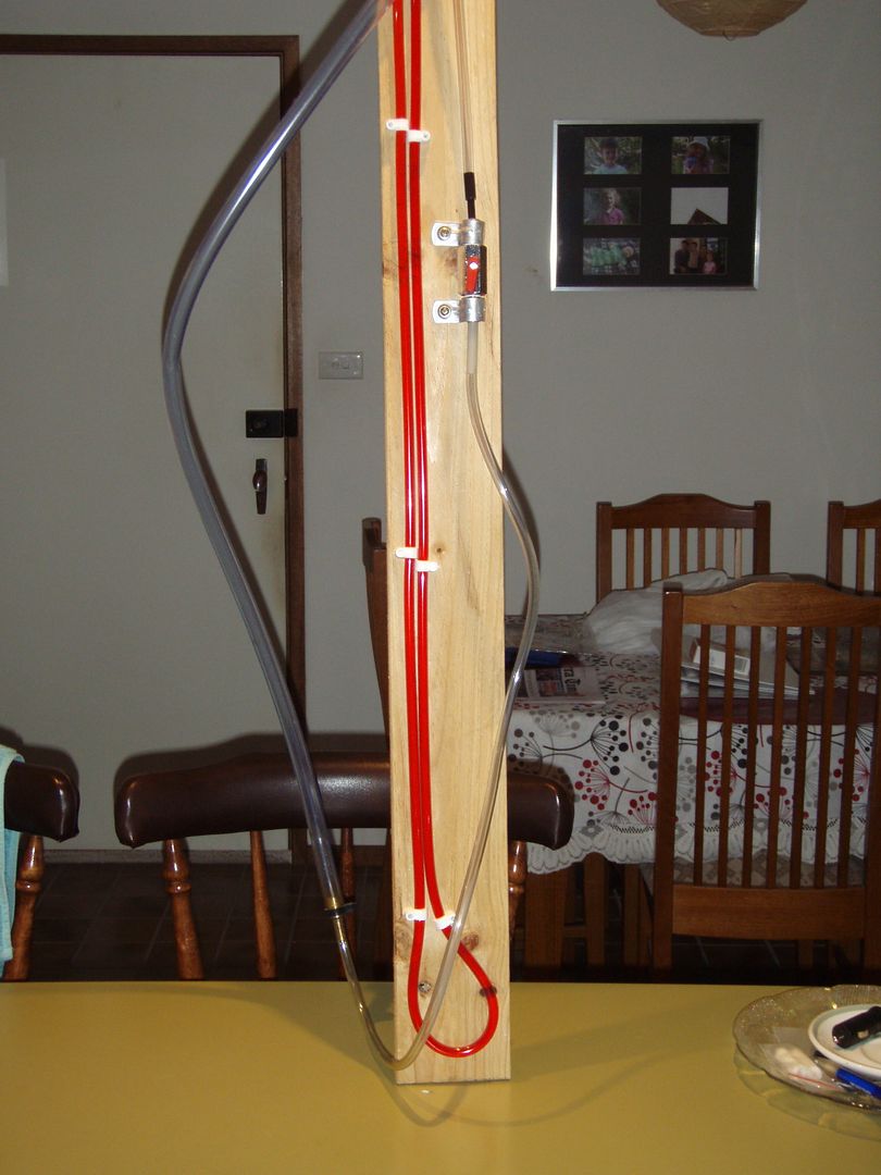
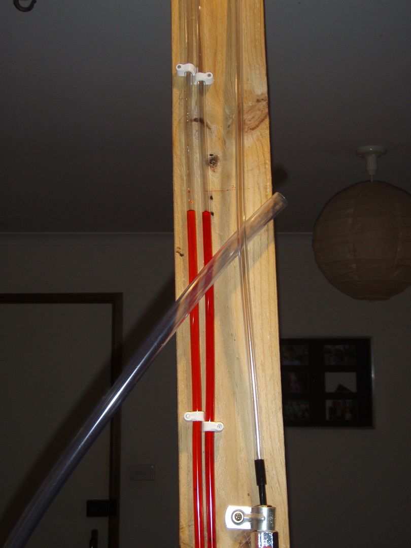
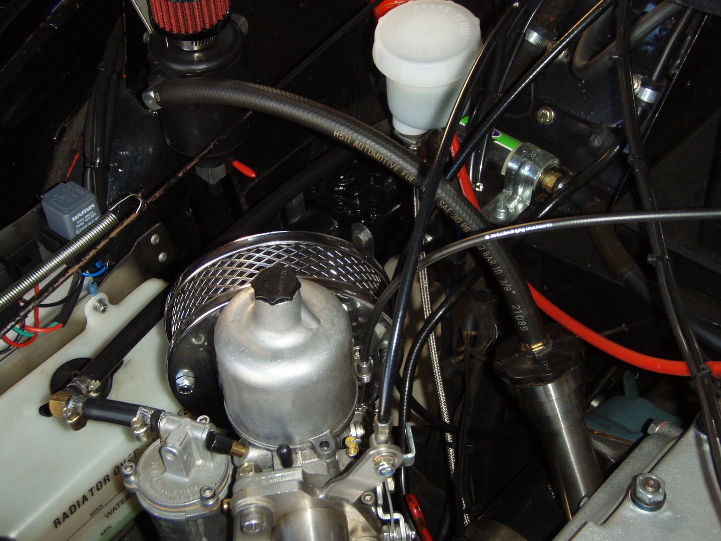
My reason for thinking that way was because I have done similar to my motor.When I built my side valve motor I decided to reduce the problem of oil loss from the rear crankshaft scroll. The original 'crankcase ventilation' on a MM is by a pipe running down from the side plate tappet cover in the hope that when the car is mobile a vacuum is drawn by the air passing past the bottom of the pipe drawing air from the crankcase. This system was as good as useless often spewing oil out of the pipe and doing very little to solve the rear scroll leak. The system I am using is to replace the tappet cover with a solid one machined from 1/2 inch alloy plate with a tapped hole to accept a fitting for 10 mm. oil proof hose. This hose is run up to a PCV valve (on the intake side of the blower). The air inlet to the motor is via a specially made stainless oil filler tube with a machined adaptor to accept an A Series oil filler cap TIG welded to the tube. The cap is connected to a catch tank with a filter. The attached images show a manometer I made to set up the system. The fluid in the manometer is water coloured with red food dye. It connects to the dipstick hole via the larger plastic tube which is a good tight fit. With the motor idling at about 950 RPM and using a non vented oil filler cap there was a vacuum of 4.8 inches water gauge drawn. With a tall vented filler cap the vacuum dropped to 1.2 inches WG. With no oil filler cap the vacuum was zero. A lot of research led me to believe that it is necessary to have some vacuum in the crankcase to reduce the escape of oil past the scroll and to also have a flow of air through the crankcase to purge water vapour and other combustion byproducts which would otherwise result in a build up of 'mayonaise'. The tube shown in the image from the filler cap to the catch tank has a 3.8 mm. dia. restrictor in it. This results in a crankcase vacuum of 1.8 inches WG the rest of the maximum 4.8 inches is used to purge the crankcase of water vapout etc. This system has been in use for about three years or so and works quite well.
Bob