Page 5 of 14
Posted: Sun Nov 22, 2009 1:33 pm
by taupe
Posted: Mon Nov 23, 2009 1:17 pm
by rich-legg
Looking good

How does the upstand bellow the rear seat attach to the floor? I know the floor repair panels are not correct in this area. I've searched & searched, but I can't find anyone who has repaired this area to factory spec. I know we spoke about this briefly when I was over the other week.
BTW, no offence, but if you want to get 30% off a new digi camera, go to
www.fuji.co.uk/shop and use promo code P832A4V3T8WKG

Posted: Mon Nov 23, 2009 8:20 pm
by taupe
Hi Rich
Wait and see!
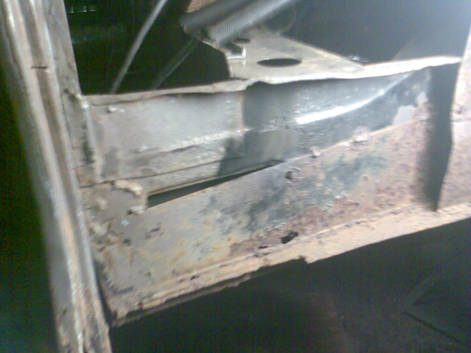
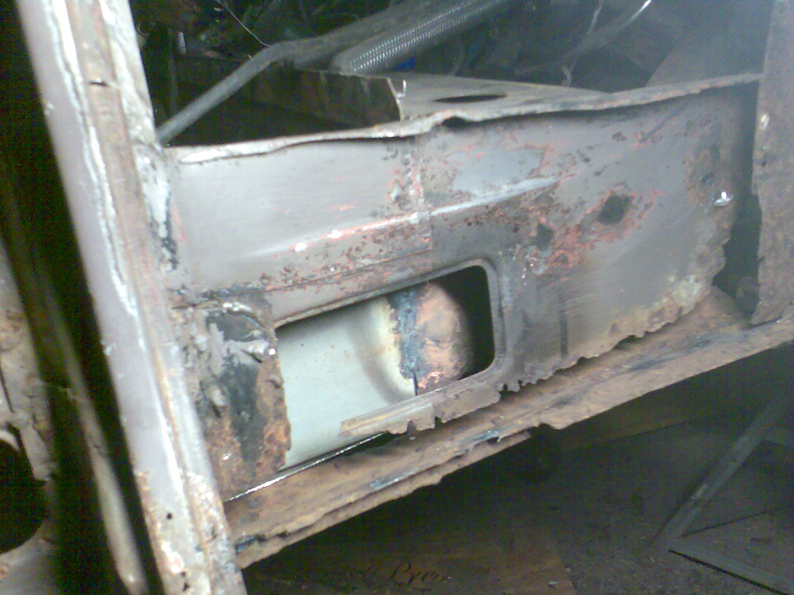
Sorry about the awful pic quality - I do have a digi camera but cant find the USB cable and disc!!!
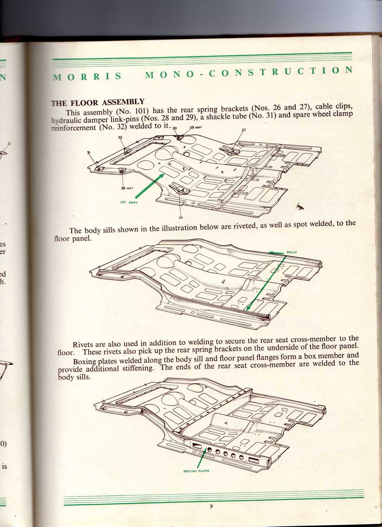
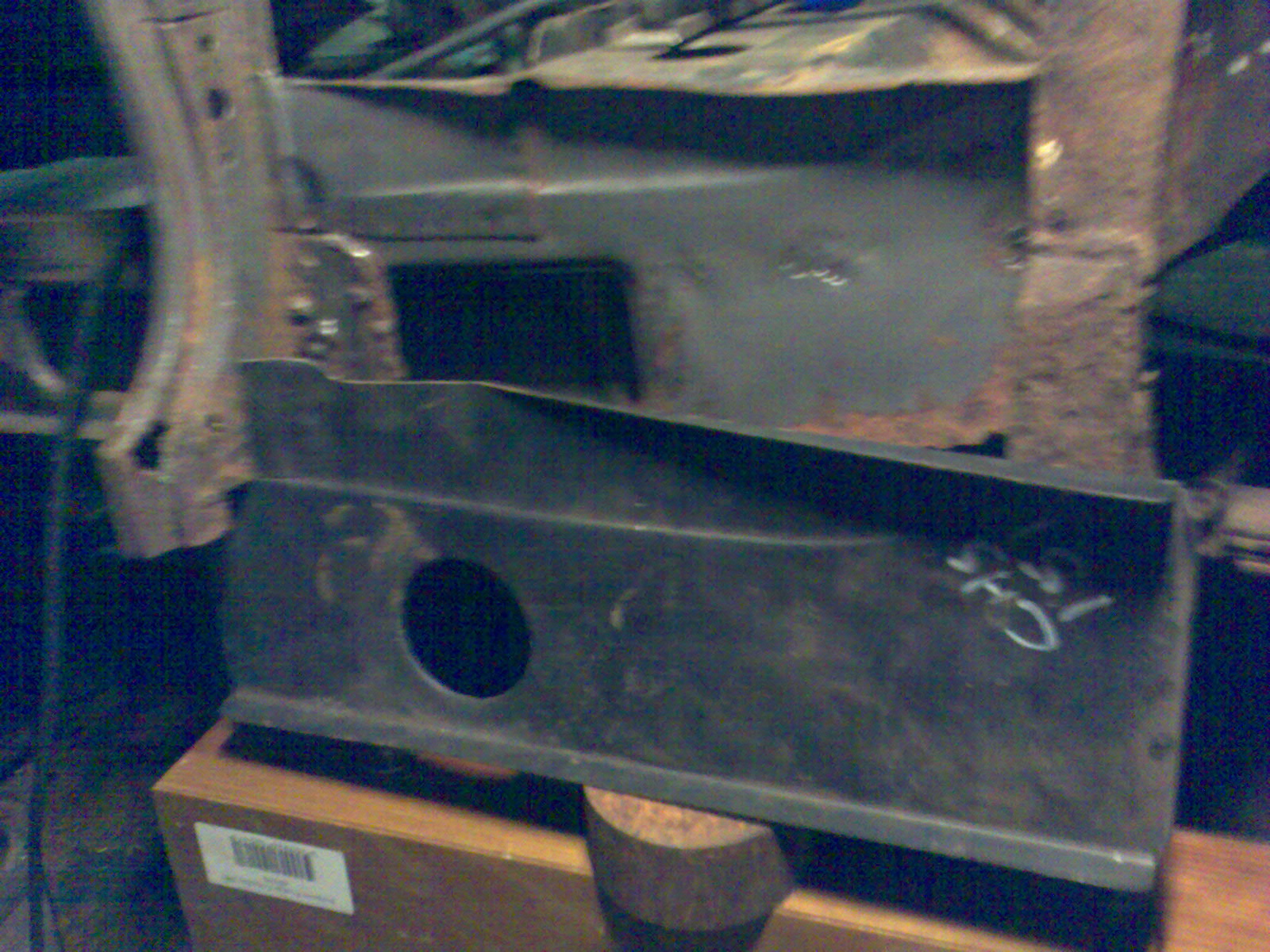
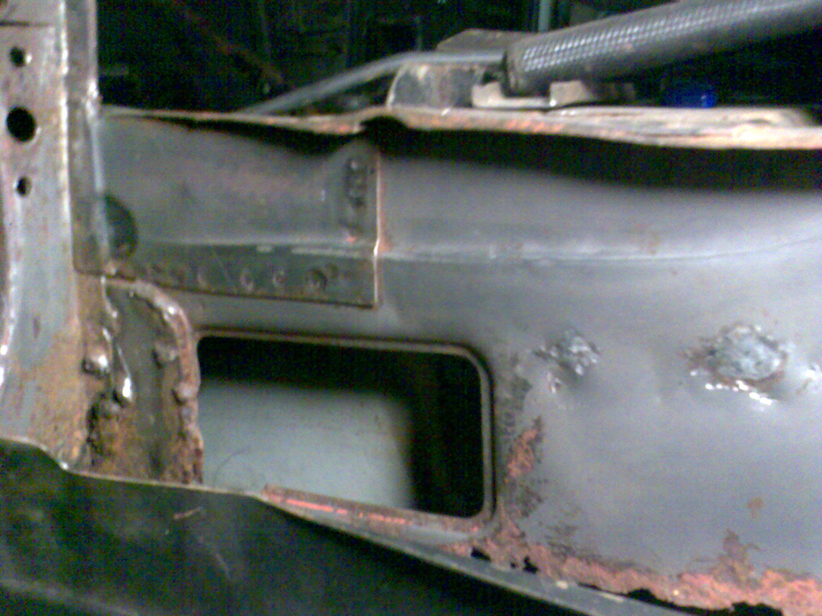
The vertical seat support panel at the back of the rear floor has a 1/2" return at the bottom facing forwards. This was originally spotwelded to the floor pan and sides of the step sills and gas welded at the bottom corners of the step sill. This is the bit in my fuzzy first and second photos!!
The spring hangers front edges also sit under this seam and have 2 hot rivets right thro the floor and the 1/2" return on either side. I havent ground the rivet heads off yet but I am guessing 3/16" or 1/4" rivets were used.
The rear of the spring hanger also has two hot rivets each side. The two inner ones go thro the floor pan and the 1/2" rear facing return of the seat support. The outer two go through the floor pan and the 3/4"return on the side chassis rail (rear extension of the step sill). Incidentally this helps a lot with alignment of the spring hangers.
Im going to tackle the repair when the shell is rolled but I intend to replace the section of floor pan under the seat support and the spring hanger plate first before finally welding in the rear floor panel - Im going to extend the front edge of the under seat floor repair to bring it to about 3mm before the rear floor pan starts and spot weld it in place along the 1/2" return 'as original'. This will allow the rear floor pan to sit on the outer edge of the 1/2" return and I will then seam weld it from underneath.
At the sides I will spot weld the spring hanger plate to this return but it will sit further forward, part way into the rear floor pan which I will cut out and seam weld to suit. Once this is done I will drill and fit the hot rivets or I might just plug weld right thro.
I expect it will be a few weeks before I tackle this and post pics so if you need to come over I can show you!!
Regards
Taupe
Posted: Mon Nov 23, 2009 10:37 pm
by taupe
Rich
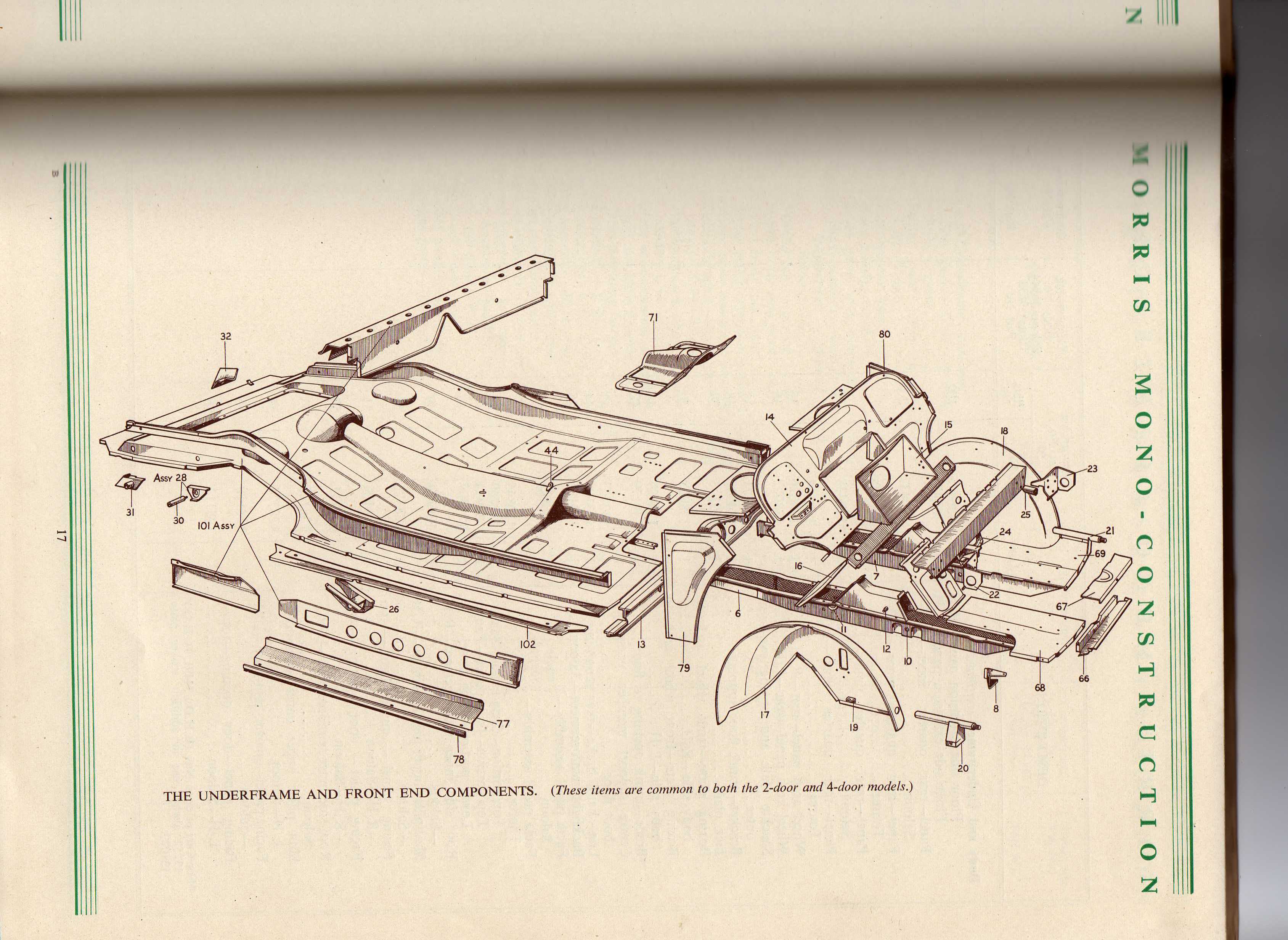
Heres a couple of pages detailing the floor make up - the front rivet holes can be seen in the second image just above and left of No.44 in the middle of the pic
Regards
Taupe
- floor make up.jpg (196.88 KiB) Viewed 3384 times
- Flooor.jpg (681.43 KiB) Viewed 3384 times
Posted: Mon Nov 23, 2009 11:11 pm
by PSL184
rich-legg wrote:
BTW, no offence, but if you want to get 30% off a new digi camera, go to
www.fuji.co.uk/shop and use promo code P832A4V3T8WKG
This guy is Chip Foose, not David Bailey

Posted: Tue Nov 24, 2009 12:29 am
by d_harris
seriously impressive!
Posted: Tue Nov 24, 2009 1:29 pm
by RobThomas
That looks like an interesting and useful book. What is it called (and where can I get a copy)?
Posted: Tue Nov 24, 2009 2:47 pm
by taupe
Hi Rob
Morris Mono Construction - a Morris Motors publication
They turn up on ebay occasionally but are usually rather expensive!
Posted: Wed Nov 25, 2009 10:48 pm
by taupe
Posted: Thu Nov 26, 2009 7:26 am
by mogbob
Taupe
It's " lookin good "....very satisfying when another section of a resto comes together.On to the next one !!
Well done...quality work.
Bob
Posted: Thu Nov 26, 2009 9:20 pm
by linearaudio
Excellent, excellent workmanship. So rewarding to beat hell out of a bit of steel sheet and produce it all yourself
Your reference to "hank bushes" took me back a bit- must be 30 years since I've heard that term!
Keep up the good work!
Posted: Thu Nov 26, 2009 11:12 pm
by PSL184
This is one resto topic that I always look forward to updates on - partly because I always "try" and make my own panels but mostly because of the excellent work that you are doing. Keep it coming

Posted: Mon Nov 30, 2009 10:01 pm
by taupe
Posted: Mon Nov 30, 2009 10:28 pm
by andy-harris
Taupe, I am learning sooo much from your photos, thank you. Is there a good book I can get that explains your measuring/marking out techniques - it's obviously a big part of your magic.
Posted: Tue Dec 01, 2009 4:52 pm
by billlobban
It will all be expained in Taupe's new video alternatively we'll all have to wait for the next installment. Fantastic
Posted: Tue Dec 15, 2009 9:49 pm
by taupe
Hi
Ive been looking at the sill components needed to extend out from the floors.
Ive got Hadrian repair panels for the floor edge panels. These seem to be pretty good, thickness and fit wise - and now have the drain holes in as my previous post.
Ive looked at the boxing panels (the long ones with big holes all along) and the boxing extension panel, one of each came with the car when I bought it.
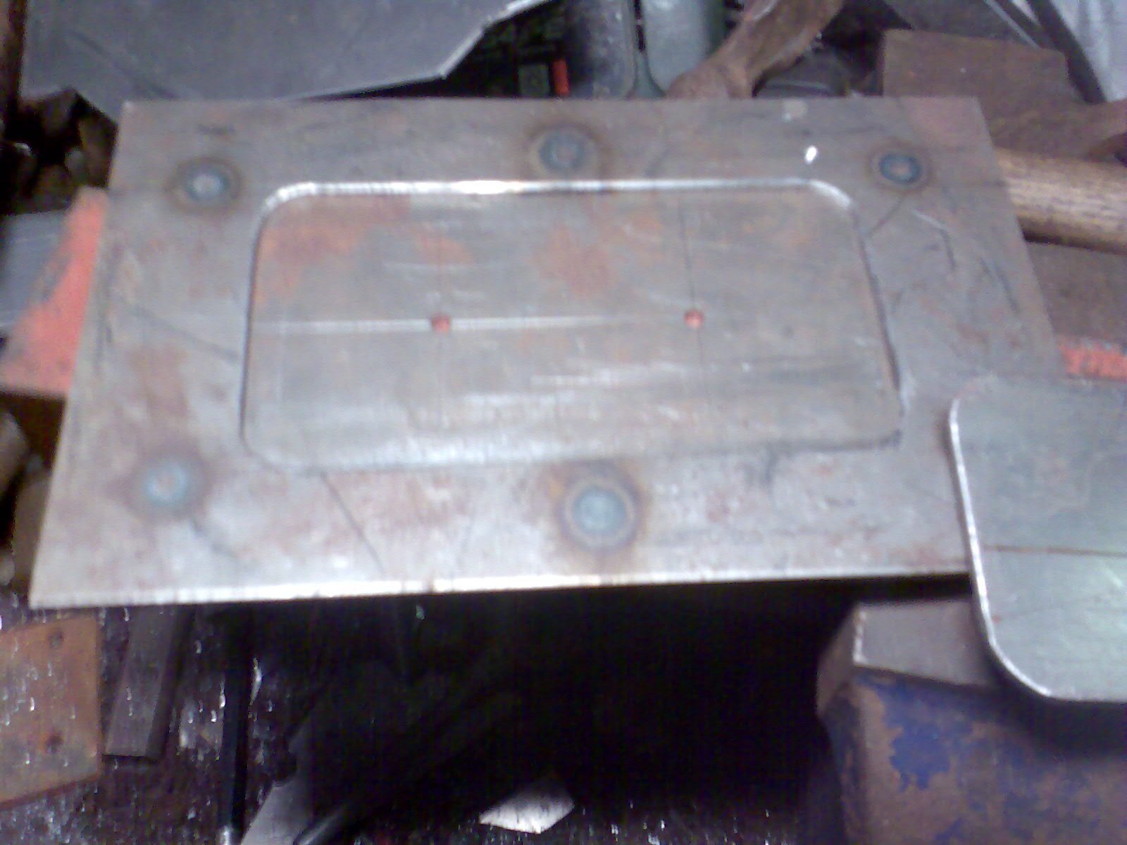
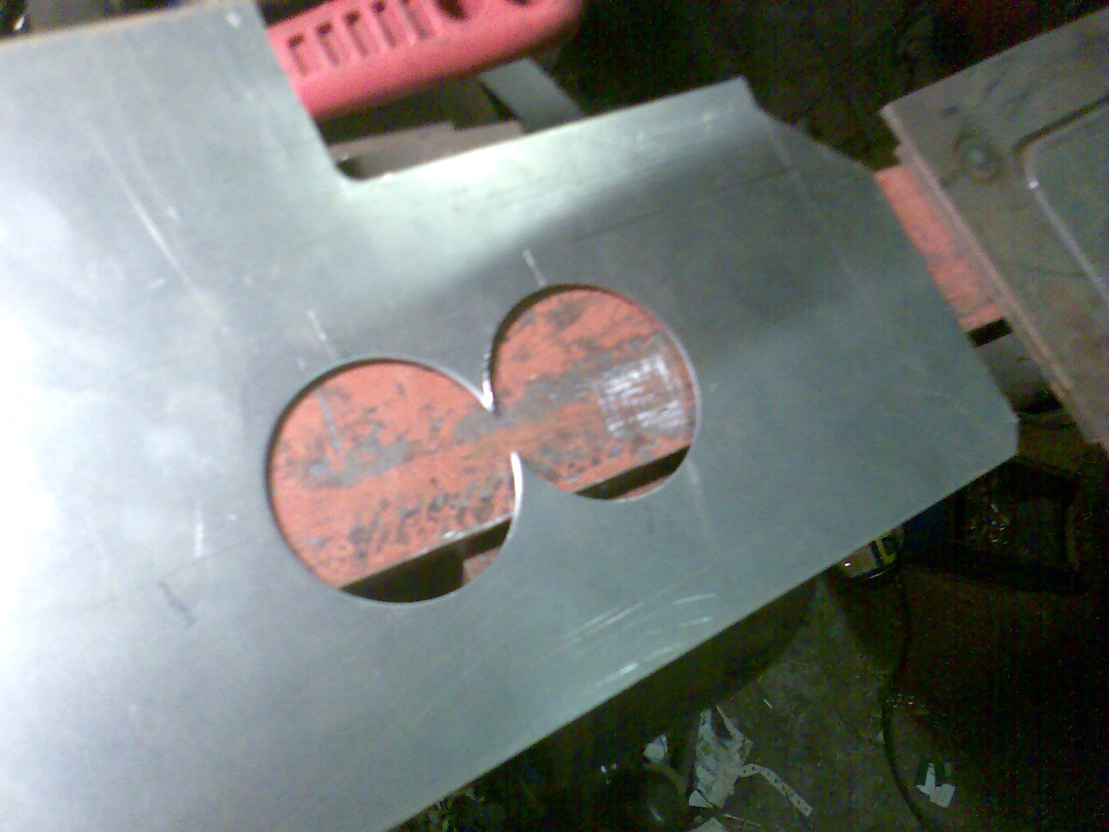
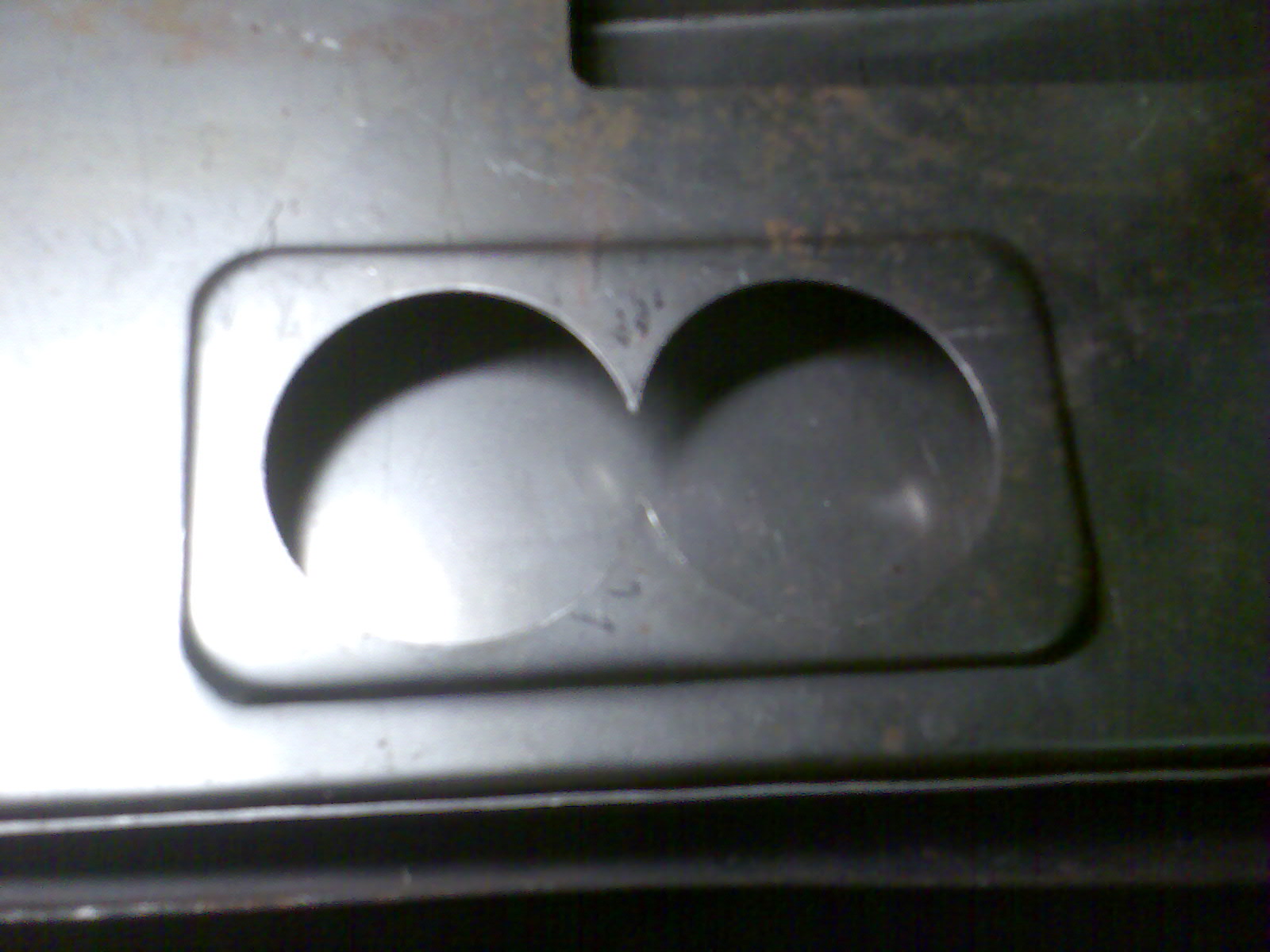
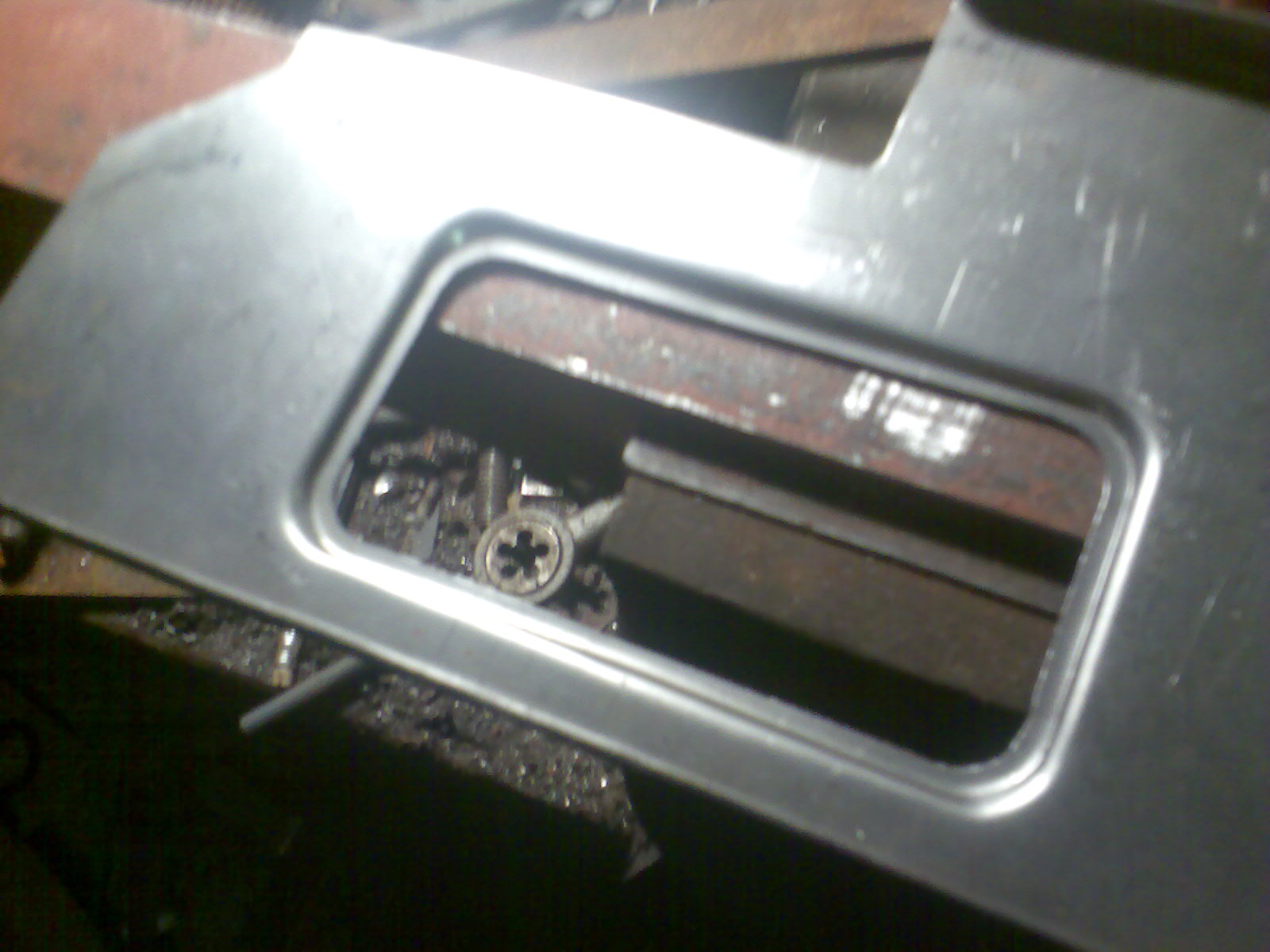
I decided that I could make the extension panel (originally with a big rectangular hole) as I only need to replace the bottom half of this panel up to the top edge of the step sill flange.
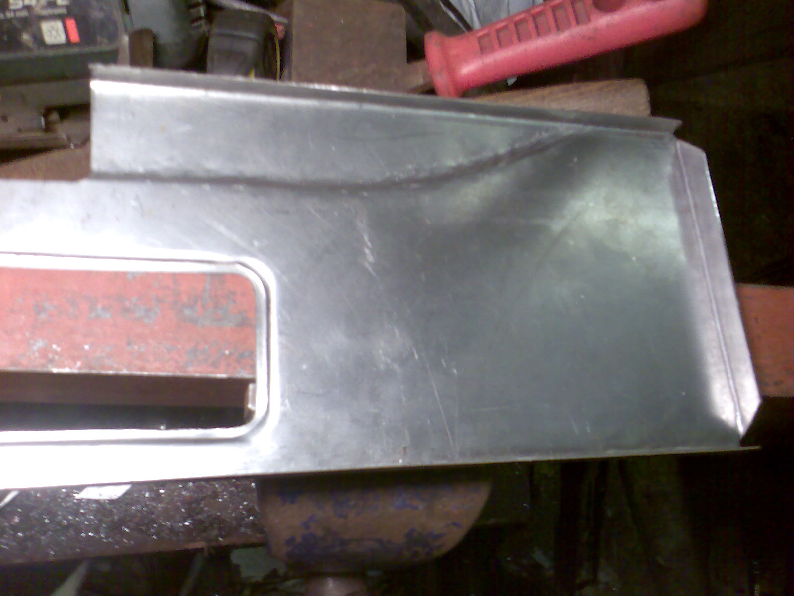
The new panel has one circular hole and was a little too long - it was also without a seperate infill panel between the seat base and B pillar - this was all built in as one panel and a strange shape at the top? I worked out the sizes after a lot of fiddling about/measuring of what was left of the original.
Once Id realised that the missing bottom edge/flange should be level and in line with the bottom edge of the boxing panel ( mine was rather bodged in this area and tilted upwards on one side and down on the other!) - it seemed obvious afterwards - and it was quite straightforward.
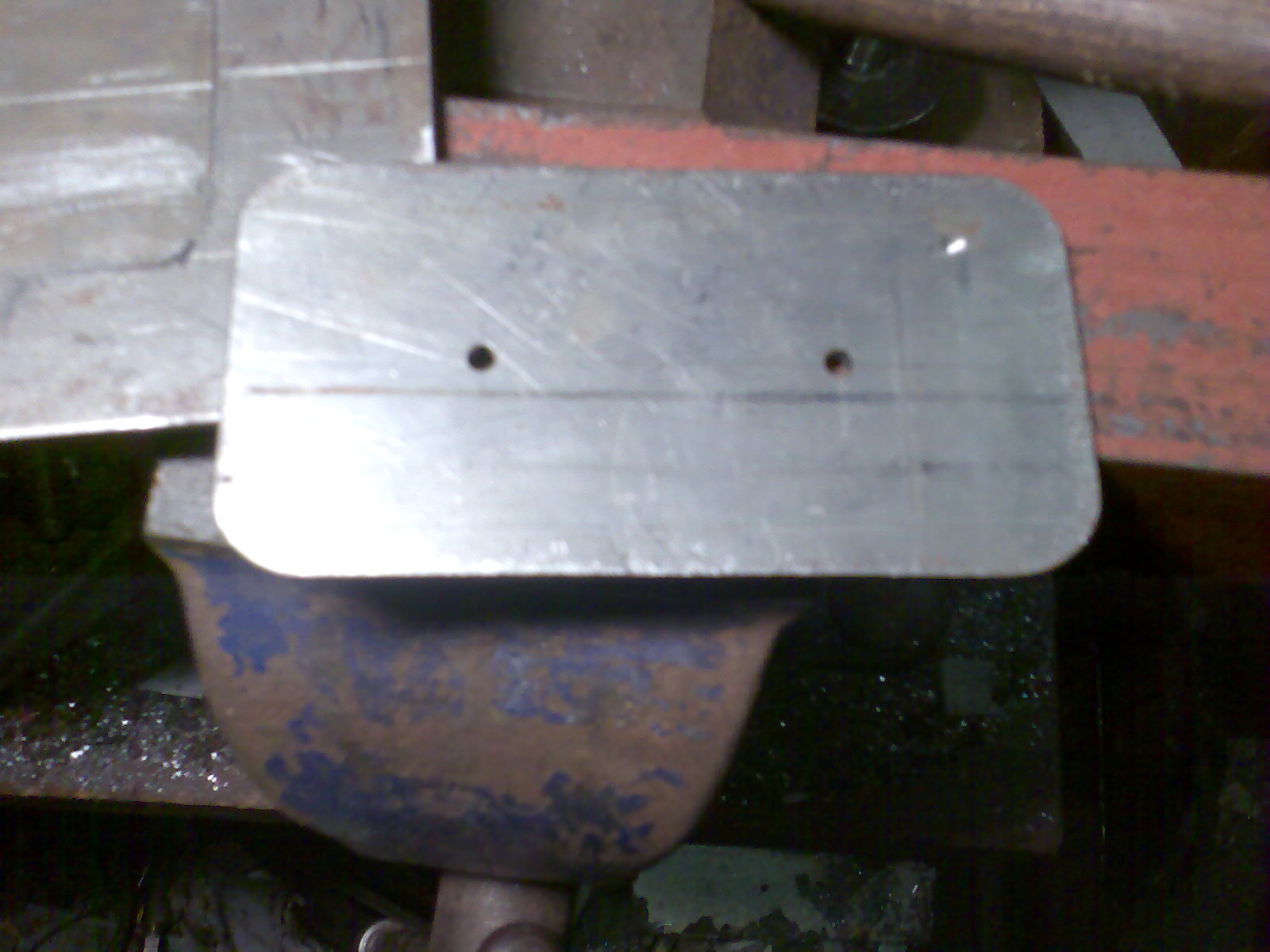
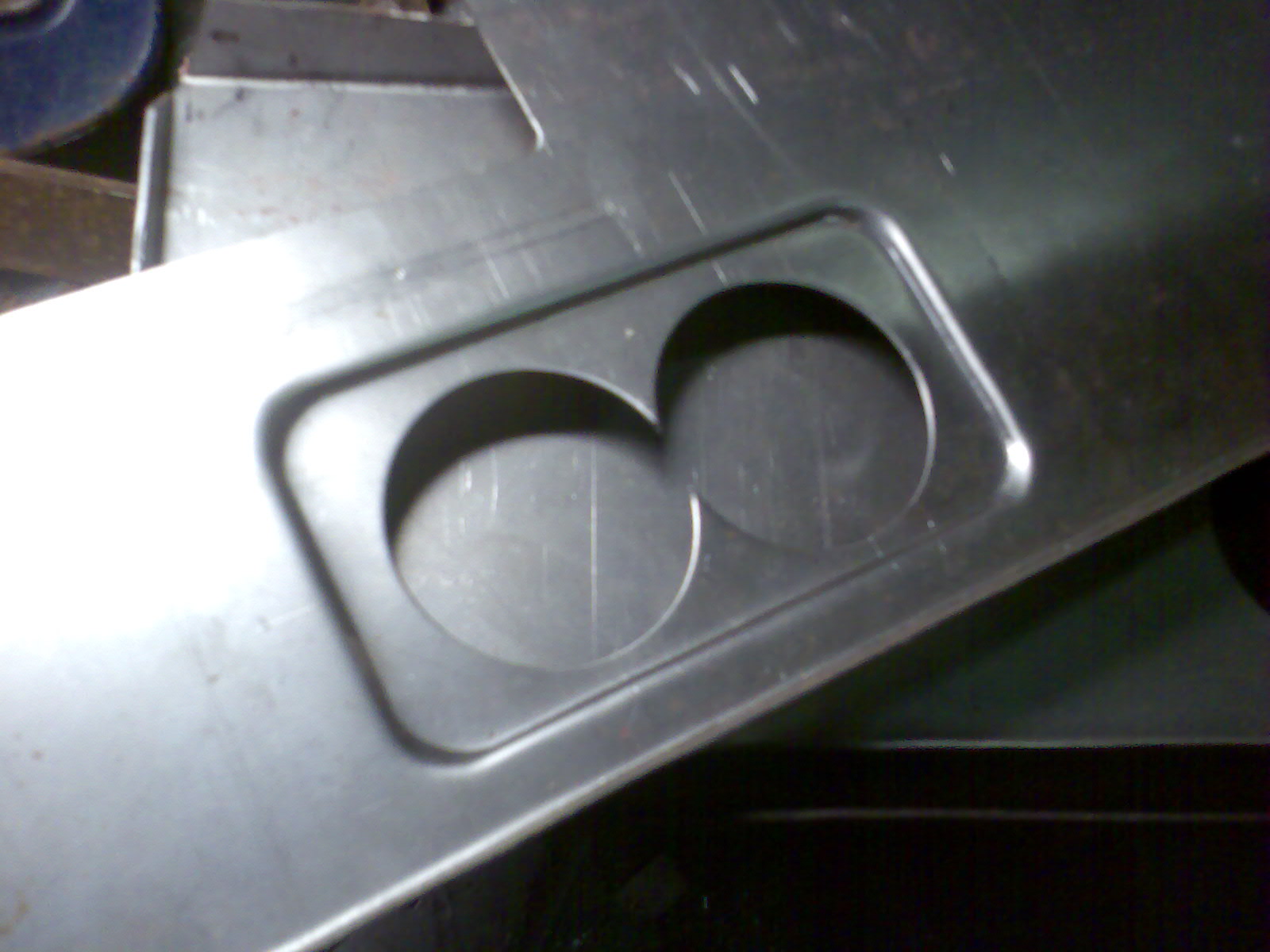
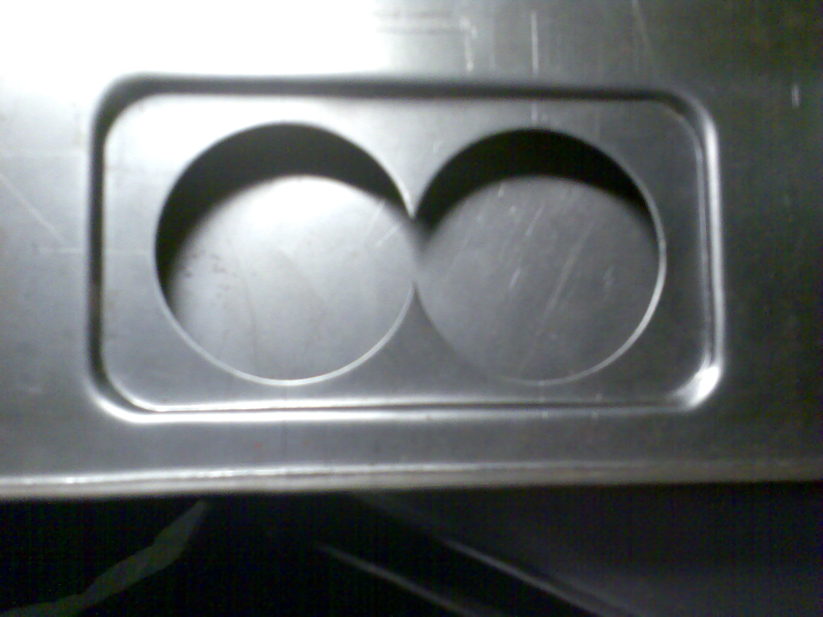
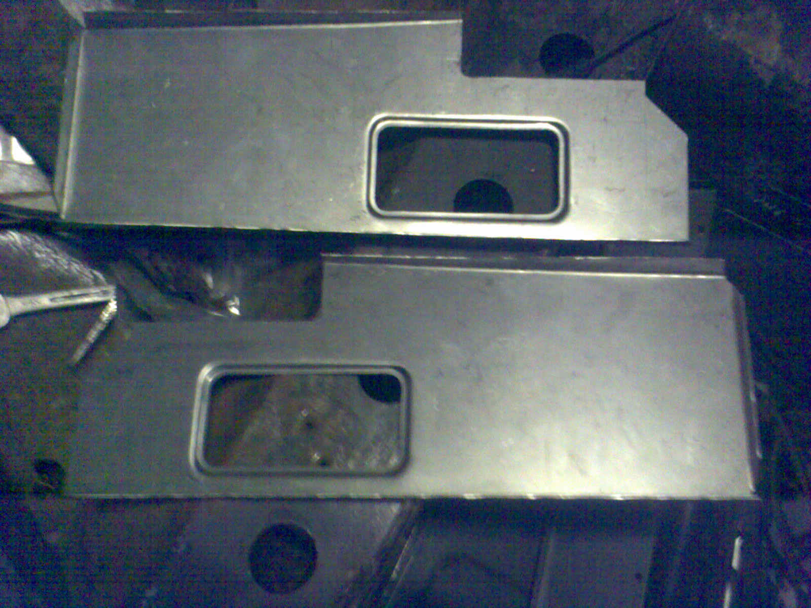
To make the panel I started by cutting out a rectangular hole in some 3mm steel, then cut a matching plate 2.5 mm smaller to act as a press tool. After cutting some big holes in the new panel to make the pressing easier, the 'tool' was then simply aligned and the plate pressed into the hole. - very satisfying results
The main long boxing panel Ive got is only 18 swg and the original was 16 swg so Im thinking about whether I need to make these too!!
I must buy the other outer floor panel that I need for the offside. Im going to use one from a two door and cut it down to match the one for the nearside Ive already done.
Here are some pics:
- Image020.jpg (405.45 KiB) Viewed 3367 times
- Image024.jpg (444.58 KiB) Viewed 3367 times
- Image026.jpg (499.57 KiB) Viewed 3367 times
- Image028.jpg (464.49 KiB) Viewed 3367 times
- Image094.jpg (290.48 KiB) Viewed 3367 times
- Image095.jpg (236.61 KiB) Viewed 3367 times
- Image100.jpg (370.15 KiB) Viewed 3367 times
- Image102.jpg (182.86 KiB) Viewed 3367 times
- Image106.jpg (202.8 KiB) Viewed 3367 times
- Image107.jpg (270.94 KiB) Viewed 3367 times
- Image108.jpg (207.77 KiB) Viewed 3367 times
- Image112.jpg (233.38 KiB) Viewed 3367 times
- Image113.jpg (497.03 KiB) Viewed 3367 times
- Image098.jpg (252.54 KiB) Viewed 3367 times
Posted: Tue Dec 15, 2009 10:06 pm
by Dean

I'm lost for words!
Posted: Wed Dec 16, 2009 10:54 am
by mogbob
I said "quality work " before....... on reflection that doesn't do it justice !!
Bob
Posted: Wed Dec 16, 2009 1:15 pm
by Ian46
When does the book come out!
Ian
Re: Rose Taupe Traveller Restoration- update 16
Posted: Mon Jan 11, 2010 11:01 pm
by taupe
Hi
Just a mini update on progress.
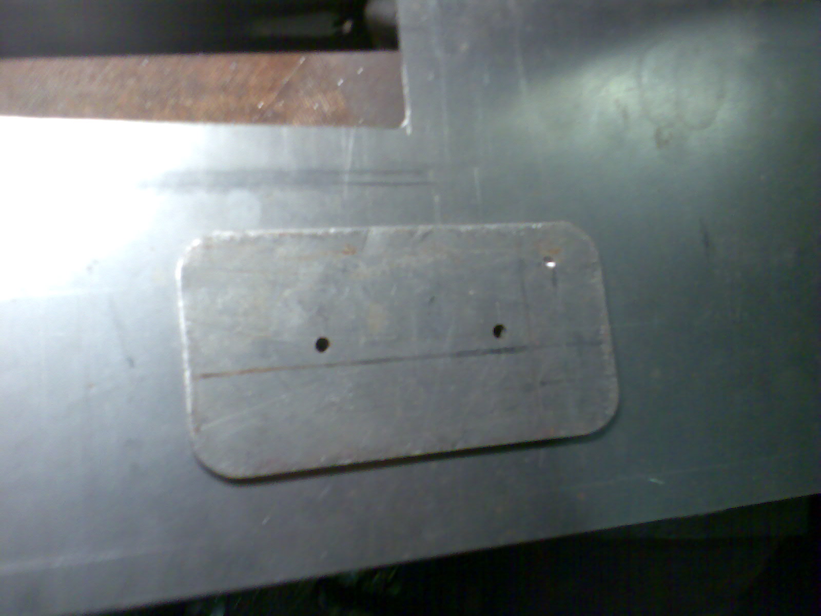
Its been rather cold for doing metalwork so I have been getting on with a few ancillaries such as replacing the heater seals, overhauling switches etc. I did however make up two cover panels for the underside of the timber just behind the B post. These are pretty much as the repair panels available but do have the upturned tab into the rear wheel arch which sits under the rear wing and closes the gap between wing and timber at the bottom.
Ive nearly finished making my heavy duty front end alignment jig - Im itching to get the car rolled over now. Ive used ground flat steel for the main reference members as I want to ensure accuracy and bright steel plate is often a bit out of true. Its been quite challenging marking out, drilling etc to the accuracy required with dimensions such as 12.437" , 13.312" etc required to be attained - so its been out with the vernier calipers etc. I guess its not actually that critical as long as its all nice and square and I dont allow multiple measurements each out by a fraction to add up to say as much as 0.5mm out.! There is some tolerence built into the fixture any way.
I guess theres no point having an alignment jig if
its out of alignment before you start.
Ive turned up the lower suspension eye checking bushes in bronze and pressed them in to the lower jig tube and now have a good fit with the steel checking pins - these check the eyebolt holes in the main chassis legs and are critical to the steering geometry. Normally you would ensure this by carefully marking and taking check dimensions before removing the old chassis leg but if the front end has been bashed or the eye rotted right out then its just guesswork without a jig.
The main sides of the jig are detailed to be 1/4 plate but cutting this to the required accuracy was going to be very difficult and time consuming so Ive opted for 1.5mm steel and reinforced with 2x2x1/4 angle. It should end up a lot stronger than the 1/4 plate anyway. Ill be posting some pics as soon as its finished. This is what im aiming for:
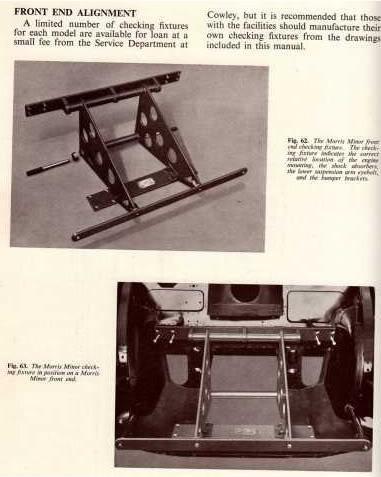
- jig.JPG (28.67 KiB) Viewed 3366 times
Ive tidied up the wiring harness which was in surprisingly good condition and just needed a couple of short lengths of damaged wire replacing.
Im considering having the run to the back of the car rebraided by Autosparks as detailed in another post under Electrical or might just use self amalg tape.
Sorry no pics at the moment - will post some more soon....