Page 1 of 1
Maestro engine
Posted: Sun Feb 27, 2022 8:02 pm
by kevin s
My son has picked up a short maestro 1275 engine for not to much, he wants to build it into the minor. We plan to use it with an mx5 gearbox and flywheel, the mazda flywheel apparently goes on with only some minor machining, for the gear box we will get a laser cut adaptor plate made.
We do need to find a head but there seem to be plenty around still, does anyone know if the head studs are the same as the minor?
Re: Maestro engine
Posted: Sun Feb 27, 2022 10:44 pm
by philthehill
The head stud pattern is the same as the Minor but that is as far as it goes.
You do need to
fit a 12G 940 head to get the best out of the
Maestro engine.
There are several variation of the 12G 940 head but for the purpose of fitting it to the
Maestro engine any 12G 940 head will be suitable.
You will need to
fit the Minor front
engine plate as the
Maestro engine is mounted differently.
It is not just a matter fitting a new flywheel and new rear
engine plate. The rear seal carrier has to be modified to suit the gearbox being used. The rear of the
Maestro crankshaft is different to the Marina/Ital
engine and has the lip seal instead of the return scroll to return oil to the sump.
Southam Mini Centre used to make kits for the
Maestro 1275
engine conversion but they have all been sold and are now out of production. If you use the search facility on here there is quite a lot of information regarding the conversion.
The
engine sits about 2" further forward which can be overcome by changing the
engine mount towers from side to side but reduces the clearance between water pump and radiator.
Here is a Minor fitted with a
Maestro engine converted by an engineer who had machining facilities. Also the rear seal adapter & seal plate as fitted to the
Maestro 1275cc
engine.
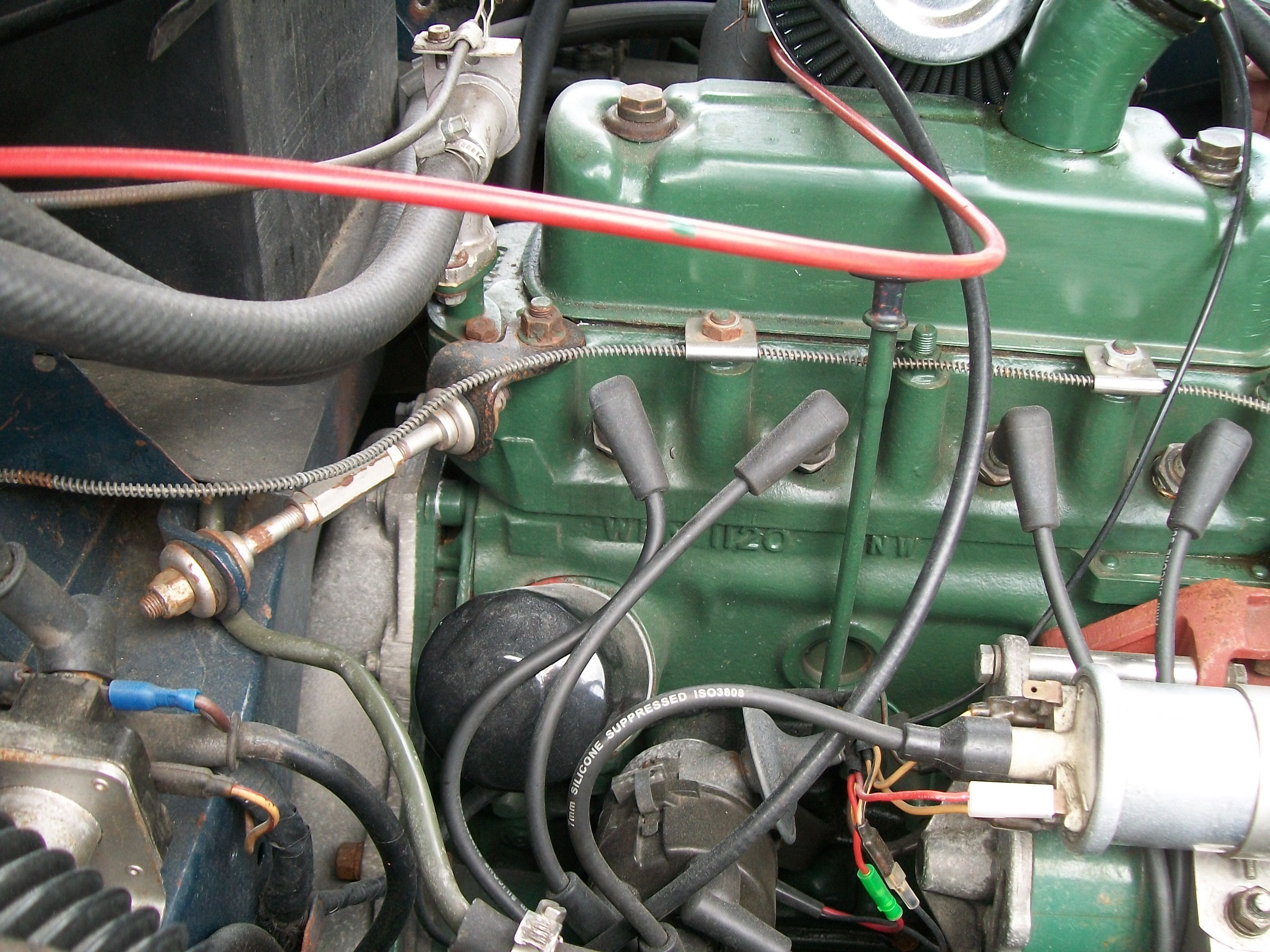
- Maestro engine 1.JPG (1.32 MiB) Viewed 1943 times
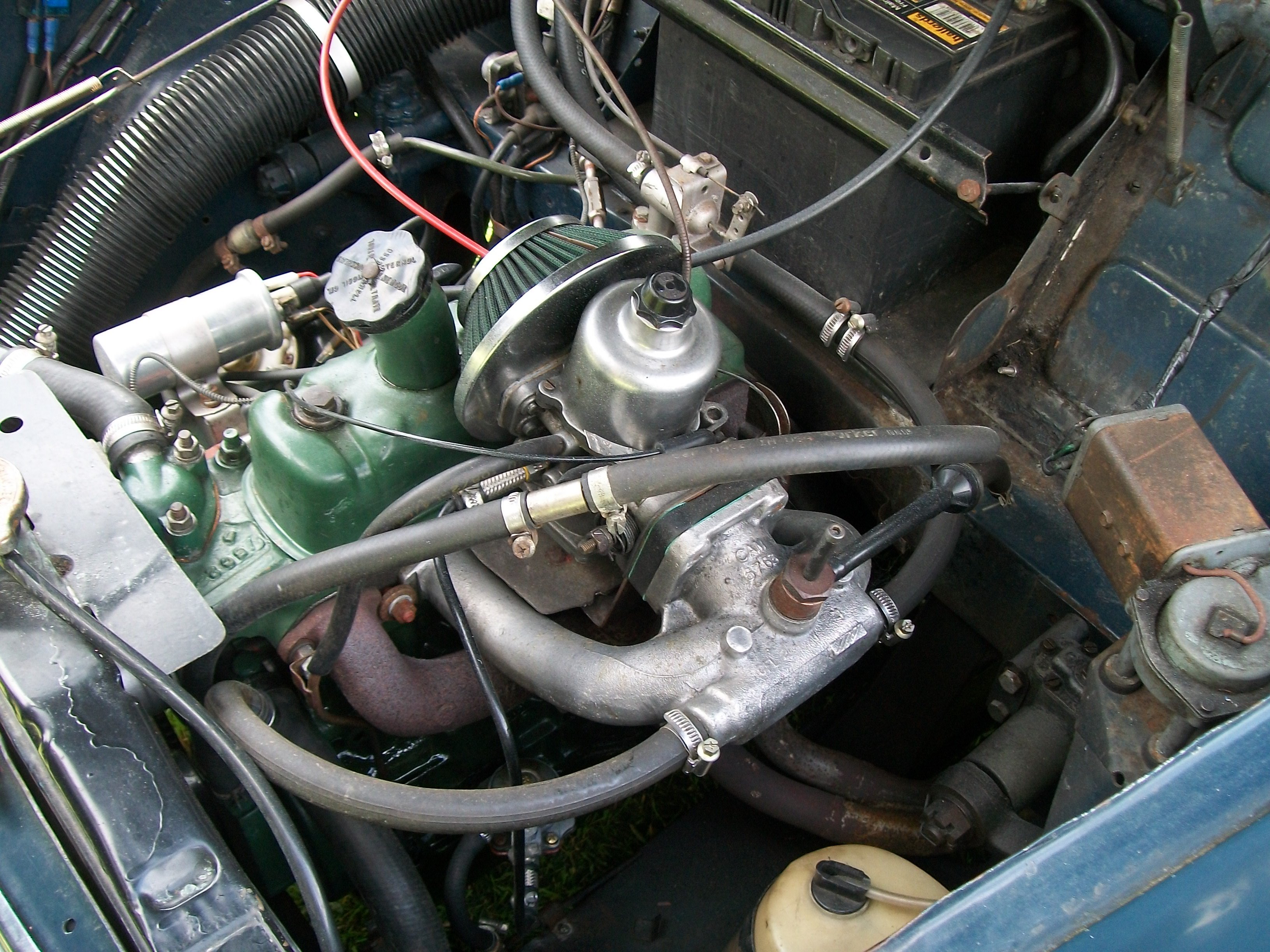
- Maestro engine 2.JPG (1.37 MiB) Viewed 1941 times
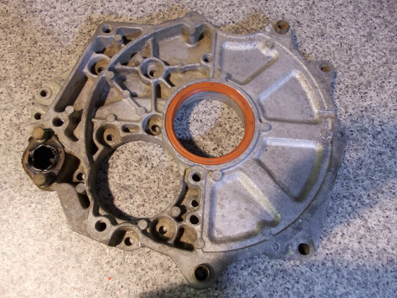
- Maestro rear engine seal plate.jpg (414.94 KiB) Viewed 1941 times
Re: Maestro engine
Posted: Mon Feb 28, 2022 9:06 pm
by kevin s
Yes we have a similar idea for the rear, the current plan is to machine the maestro backplate down and sandwhich it with a flat steel plate similar to the standard one but with a bigger hole in the centre .
How much we machine the maestro plate will depend on where the flywheel ends up. Apparantly the mx5 uses the same 6x65 bolt pattern as the maestro A series, the end of the maestro crank is a slightly bigger diameter so the back of the flywheel will need a tickle on the lathe, also one of the maestro holes is offset so one of the flywheel holes will need elongating which should be doable on the mill. The Mazda flywheel also carries the pilot bearing so once we have this mounted the rest should fall into place.
We might even try photogrammetry to scan the engine and box then design it in cad, we have a small laser cutter so could even try making a mdf trial part before we commit to laser cut steel.
The only part we are not sure about is the starter motor, the mx5 gearbox mounted position might foul the A+ oil filter (we won't be using the distributor), it may be we can get away with a remote set up or a smaller filter, if it's close we could always index the gearbox a little as well.
Re: Maestro engine
Posted: Tue Mar 01, 2022 3:18 pm
by kevin s
Re: Maestro engine
Posted: Thu Mar 03, 2022 10:16 pm
by kevin s
Mx5 1.6 flywheel arrived today, it does indeed have bolts on the same pcd as the
maestro A series.

- rps20220303_220439.jpg (94.63 KiB) Viewed 1808 times
The crank end and flywheel recess are also identical.
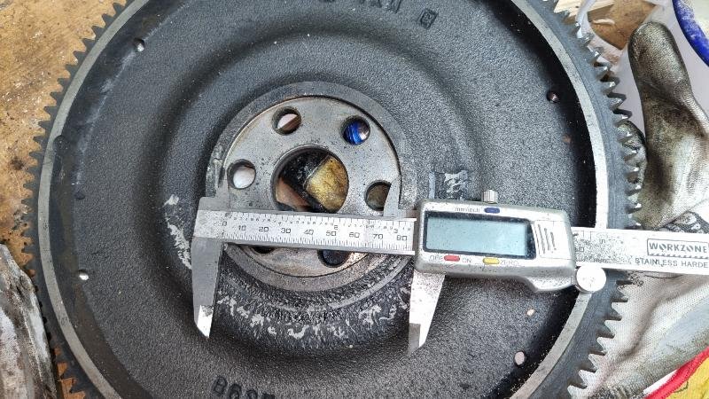
- rps20220303_220507.jpg (109.52 KiB) Viewed 1808 times
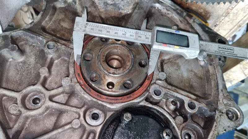
- rps20220303_220427.jpg (92.05 KiB) Viewed 1808 times
The key differences are the mazda uses m12 bolts and the meastro m10, so so sleeves made out of 12 ×1 tube will be required, the other issue is the spigot in the centre of the
maestro crank needs removing, I could do it with a grinder but I'd rather do it properly hopefully I can get the crank in our Lathe.
Re: Maestro engine
Posted: Thu Mar 03, 2022 11:15 pm
by Chipper
I'll be very interested to hear your progress on this. How did you find out a Mazda MX5 gearbox can be mated up to it?
Re. the spigot, an old trick used to be to fill it with grease then use a suitable size drift hammered in to force the grease underneath it, to create enough hydraulic pressure to force it out.
https://www.youtube.com/watch?v=Y7QztTTSyhE
Re: Maestro engine
Posted: Fri Mar 04, 2022 9:38 am
by philthehill
Bread instead of grease pushed into the spigot bush and hydraulically compressed with a close fitting drift is very good for removing the spigot bearing.
As regards the flywheel holding bolts - I personally would machine out the flywheel bolts holes and fit thicker spacers around the bolts. 1mm thickness tube spacers are too thin. I would be looking for tube spacers of at least 3mm wall thickness. The tube spacers should be a tight fit in the flywheel. That would also help get around the offset bolt. Use Loctite bearing lock to secure both the flywheel bolts and spacers.
Having had a flywheel come loose on a 'A' Series engine I am all to well aware of the damage a loose flywheel can cause.
Re: Maestro engine
Posted: Fri Mar 04, 2022 11:32 am
by kevin s
The bolts won't be locating the flywheel the good fortune that as on the Mazda the flywheel is a tight fit on the outside of the crank and will centralise it, the Maestro bolts also have a large head so will cover a good area of the crank to give a good clamp and Loctite patches, at the end of the day the bolts shouldn't be carrying any shear load it should be the clamp force between the flywheel and crank which hold it together, I did think about stepped bolts with 12mm shank and m10 thread but they would be machined and have nowhere near the strength of a rolled thread, the other option I'm mulling over is to drill and re-tap the crank to M12 x 1.5 as per the Mazda.
The crank issue is that it is part of the crank which sticks out of the end, I think the pressed steel clutch which on the Maestro bolts to the crank locates on this, the Mazda needs a flat face on the crank as the pilot bearing presses in the centre of the flywheel and abuts the crank, the other option would be to machine the flywheel to suit then make a bronze pilot bearing to go in the end of the crank. all things to mull over.
How did we come up with the idea - I have a 1.8 m5 and love the gearshift, I also had a spare gearbox kicking around, I have all bar the slave cylinder mounting plate made a kit to attach one to a 1098, when we got the maestro engine some research on line showed that someone had started doing this on an midget and found the flywheel fitted with some machining. (thread dried up so no idea if he finished it).
Re: Maestro engine
Posted: Fri Mar 04, 2022 12:18 pm
by Chipper
philthehill wrote: ↑Fri Mar 04, 2022 9:38 am
Bread instead of grease pushed into the spigot bush and hydraulically compressed with a close fitting drift is very good for removing the spigot bearing.
Having had a flywheel come loose on a 'A' Series
engine I am all to well aware of the damage a loose flywheel can cause.
Ah yes, the good old damp bread trick!

What damage was done, and do you have any photos?

Re: Maestro engine
Posted: Fri Mar 04, 2022 12:55 pm
by philthehill
The damage to the crankshaft was caused by a unsuitable grade metal shim supplied as part of a crankshaft rear lip seal fitting kit.
The metal shim was too soft allowing the shim to compress and with use the flywheel bolts and flywheel to loosen. The fitment of the shim lifted the flywheel off the crankshaft register. The crankshaft and flywheel were originally from a 1275cc Midget.
The damage was to the mounting bolt holes on the flywheel and the rear end of the crankshaft.
The crankshaft and flywheel were extensively modified so the replacement parts and which required modifications cost well over £1000 back then and caused a 6 month absence from motorsport whilst the new parts were sourced and modified.
Thankfully I realised what had happened & stopped the engine before any more serious damage occurred.
Subsequent to the damage I would not recommend the fitment of a lip seal kit which requires a shim between flywheel and crankshaft.
Having gone back to the original scroll seal it works perfectly well and the engine has completed many hours running in sprints and speed hill-climbs.
Unfortunately no photographs.
Re: Maestro engine
Posted: Fri Mar 04, 2022 1:32 pm
by kevin s
I work in the modern automotive world, what you describe is why nobody uses sprung or tab washers anymore, design the joint right (perfectly mating surfaces with enough stretch in tbe bolt to maintain tension and no compressible elements) and it stays secure, I always use loctite on critical fastners and paintmark visible ones as well.
On something like a flywheel the bolts should only provide clamp force, friction between the flywheel and crank should transmit the torque, if the bolts start seeing shear loads the flywheel is already moving on the crank and it's only a matter of time until something fails.
Re: Maestro engine
Posted: Fri Mar 04, 2022 1:34 pm
by kevin s
I've also just reviewed it with my son we have agreed to leave the crank as it is and machine the flywheel to suit, then make a bronze pilot bearing.
Re: Maestro engine
Posted: Fri Mar 04, 2022 3:06 pm
by philthehill
As regards the bolts - they will be in rotational shear - that is they will have shear against the flywheel rotating. I had a similar problem with the alloy flywheel fitted to my 1380cc comp
engine. Overcome by fitting ARP bolts and utilising the two dowels in the end of the crankshaft to flywheel flange as well as the register.
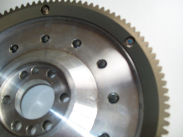
- Alloy flywheel 1.jpg (34.08 KiB) Viewed 1738 times
Re: Maestro engine
Posted: Fri Mar 04, 2022 4:52 pm
by kevin s
there are 2 dowel holes in the end of the crank, It would be difficult to drill them accurately in the flywheel though, did think about getting them as close as I can then reaming them both together.
Re: Maestro engine
Posted: Fri Mar 04, 2022 7:00 pm
by kevin s
philthehill wrote: ↑Fri Mar 04, 2022 3:06 pm
As regards the bolts - they will be in rotational shear - that is they will have shear against the flywheel rotating. I had a similar problem with the alloy flywheel fitted to my 1380cc comp
engine. Overcome by fitting ARP bolts and utilising the two dowels in the end of the crankshaft to flywheel flange as well as the register.
Alloy flywheel 1.jpg
I've always wondered about the longevity of aluminium flywheels, many years ago was heavily involved on one of the first high performance turbo engines, the alloy relaxing under the head bolts and consequent loss of Torque was a major problem, we ended up with large hardened steel washers under the bolts to reduce the problem.