mogbob wrote: ↑Sun Feb 25, 2024 12:30 pm
The pipework simply joins the two inlet connections and the two outlet connections from the two individual SU pumps.
The " modern " connectors you've marked , would take the " supply" from the fuel tank and "deliver" to the carburettors.
Bob
No it doesn't. The pumps are not parallel, they're in series a circular circuit with 2 connections.

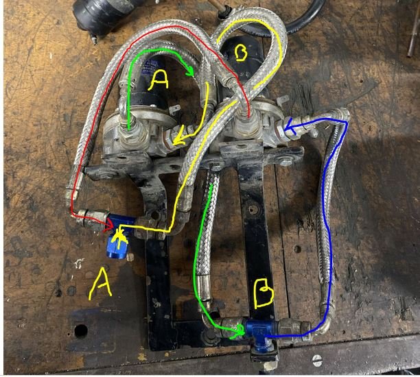
We have 2 connections A & B and we have 2 Pumps A & B.
Assume for a moment that Connection A is the Inlet.
Pump A sucks the supply in at Connection A and the liquid, lets assume it's fuel, coloured Yellow goes into Pump A and comes out on the Lime Green arrow.
Lime Green goes around to Connection B. Is that the outlet?
Because it's on the inlet to Pump B... The now Blue Line is sucked up by Pump B, so diverting some of the flow to 'Outlet' B...
The Blue Line enters Pump B and outputs as Red where it....joins Inlet A to feed Pump A.
If you change the Connection to work the other way around, it's still the same result, it's a Loop..A to B to A to B...
.
.
- PUMP To Where2.JPG (98.18 KiB) Viewed 9760 times


